Mazda CX 7. Manual - part 142
CONTROL SYSTEM [L3 WITH TC]
01-40–9
01-40
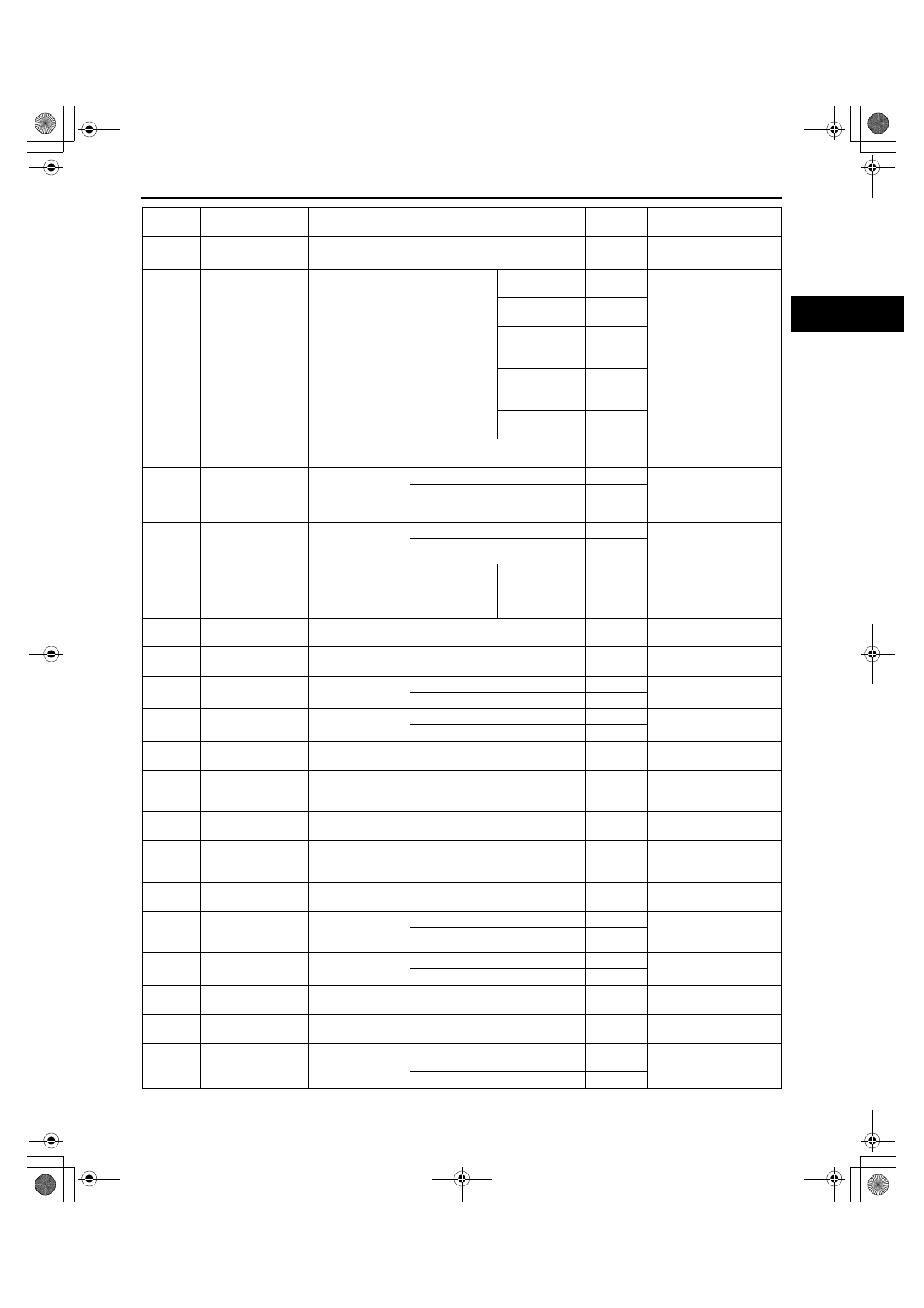
1AO
— —
—
—
—
1AP
— —
—
—
—
1AQ
Cruise control
switch
Cruise control
switch
Ignition switch
to the ON
position
ON/OFF switch
pressed in
Approx. 0
• Cruise control switch
• Related wiring
harness
CANCEL switch
pressed in
Approx.
1.1
SET/COAST
switch pressed
in
Approx.
3.1
RES/ACCEL
switch pressed
in
Approx.
4.2
Except above
Approx.
5.0
1AR
IAT sensor ground
MAF/IAT sensor
Under any condition
Below 1.0
• Related wiring
harness
1AS
EVAP leak
detection pump
(pump)
EVAP leak
detection pump
Ignition switch to the ON position
Below 1.0
• EVAP leak detection
pump
• Related wiring
harness
Idling
B+
1AT
Main relay control
Main relay
Ignition switch off after 10 s
B+
• Main relay
• Related wiring
harness
Ignition switch to the ON position
Below 1.0
1AU
A/C on signal
Refrigerant
pressure switch
(high, low)
Idle
A/C switch and
fan switch on
B+
• Refrigerant pressure
switch (high, low)
• Related wiring
harness
1AV
APP sensor ground APP sensor
Under any condition
Below 1.0
• Related wiring
harness
1AW
Injector control
Fuel Injector relay
Under any condition
Below 1.0
• Related wiring
harness
1AX
Drive-by-wire relay
Drive-by-wire relay
Ignition switch off after 10 s
B+
• Related wiring
harness
Ignition switch to the ON position
Below 1.0
1AY
Ignition switch
Ignition switch
Ignition switch off
Below 1.0
• Related wiring
harness
Ignition switch to the ON position
B+
1AZ
Ground
Ground
Under any condition
Below 1.0
• Related wiring
harness
1BA
Back-up power
supply
Battery (positive
terminal)
Under any condition
B+
• Battery
• Related wiring
harness
1BB
Ground
Ground
Under any condition
Below 1.0
• Related wiring
harness
1BC
Sensor ground
HO2S (rear)
Under any condition
Below 1.0
• HO2S (rear)
• Related wiring
harness
1BD
Ground
Ground
Under any condition
Below 1.0
• Related wiring
harness
1BE
B+
Main relay
Ignition switch off after 10 s
Below 1.0
• Battery
• Related wiring
harness
Ignition switch to the ON position
B+
1BF
Drive-by-wire relay
Drive-by-wire relay
Ignition switch off after 10 s
Below 1.0
• Related wiring
harness
Ignition switch to the ON position
B+
1BG
Ground
Ground
Under any condition
Below 1.0
• Related wiring
harness
1BH
Ground
Ground
Under any condition
Below 1.0
• Related wiring
harness
2A
Throttle actuator
control (+)
Throttle body
Ignition switch off
Approx.
1.5
• Throttle actuator
• Related wiring
harness
Ignition switch to the ON position
B+
Terminal
Signal
Connected to
Test condition
Voltage
(V)
Inspection item
1871-1U-06B(01-40).fm 9 ページ 2006年3月15日 水曜日 午前10時53分