Mazda CX 7. Manual - part 131
EMISSION SYSTEM [L3 WITH TC]
01-16–9
01-16
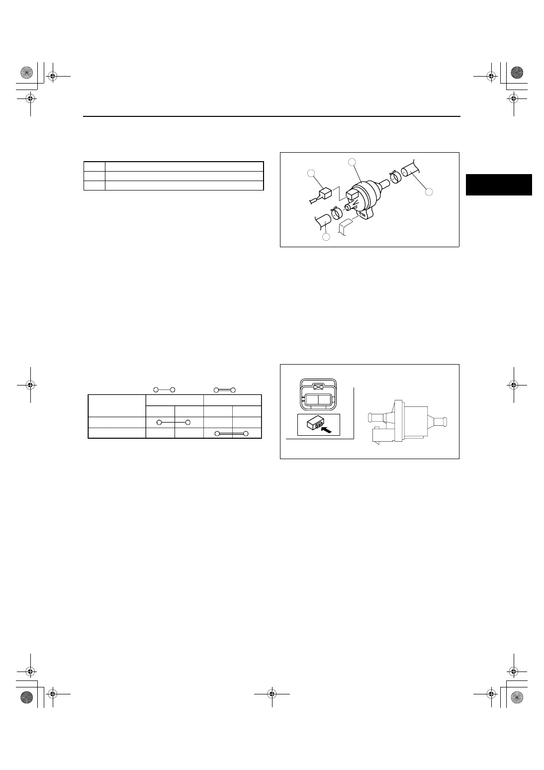
PURGE SOLENOID VALVE REMOVAL/INSTALLATION[L3 WITH TC]
id011639803500
1. Disconnect the negative battery cable.
2. Remove the charge air cooler duct.
3. Remove in the order indicated in the table.
.
4. Install in the reverse order of removal.
End Of Sie
PURGE SOLENOID VALVE INSPECTION[L3 WITH TC]
id011639800900
Airflow Inspection
Note
• Perform the following test only when directed.
1. Disconnect the negative battery cable.
2. Remove the purge solenoid valve. (See 01-16-9 PURGE SOLENOID VALVE REMOVAL/INSTALLATION[L3
WITH TC].)
3. Inspect airflow between the ports under the following conditions.
• If not as specified, replace the purge solenoid valve. (See 01-16-9 PURGE SOLENOID VALVE REMOVAL/
INSTALLATION[L3 WITH TC].)
• If as specified, carry out the “Circuit Open/
Short Inspection”.
1
Connector
2
Vacuum hose
3
Purge solenoid valve
3
1
2
2
acxuuw00000217
A
B
A
B
acxuuw00000046
Step
: Continuity
: Airflow
Terminal
Port
B
A
B
A
B+
GND
1
2
acxuuw00000045
1871-1U-06B(01-16).fm 9 ページ 2006年3月15日 水曜日 午前10時48分