Mazda CX 7. Manual - part 95


  Index      Mazda     Mazda CX 7 - service repair manual 2007 year


Search            


Content   ..  93  94  95  96   ..


Mazda CX 7. Manual - part 95


SYMPTOM TROUBLESHOOTING [L3 WITH TC]

01-03–77

01-03

Inspection Method for Sensors

1. Connect the M-MDS to the DLC-2.
2. Turn the ignition switch to the ON position (Engine off).

Note

• If the engine starts and runs, perform the following steps during idle.

3. Access the PIDs for the switch you are inspecting.
4. Shake the sensor slightly with your finger.

• If the PID value is unstable or a malfunction occurs, check for a poor connection or a poorly mounted 

sensor or both.

Inspection Method for Actuators or Relays

1. Connect the M-MDS to the DLC-2.
2. Turn the ignition switch to the ON position (Engine off).

Note

• If engine starts and runs, perform the following steps during idling.

3. Prepare the output state control function for actuators or relays that you are inspecting.
4. Shake the actuator or relay with your finger for 3 s 

after the output state control function is activated.

• If a variable click sound is heard, check for a 

poor connection or a poorly mounted actuator 
or both, or the relay.

Note

• Shake the relays too strongly may result in 

open circuits.

Water Sprinkling Method
If a malfunction occurs only during high humidity or rainy/snowy weather, perform the following steps: 

Caution

• Indirectly change the temperature and humidity by spraying water onto the front of the radiator.

• If a vehicle is subject to water leakage, the leakage may damage the control module. When testing 

a vehicle with a water leakage problem, special caution must be used.

1. Connect the M-MDS to the DLC-2 if you are inspecting sensors or switches.
2. Turn the ignition switch to the ON position (Engine off).

Note

• If the engine starts and runs, perform the following steps is idling.

3. Access the PIDs for the sensor or the switch if you are inspecting sensors or switches.
4. If you are inspecting the switch, turn it on manually.
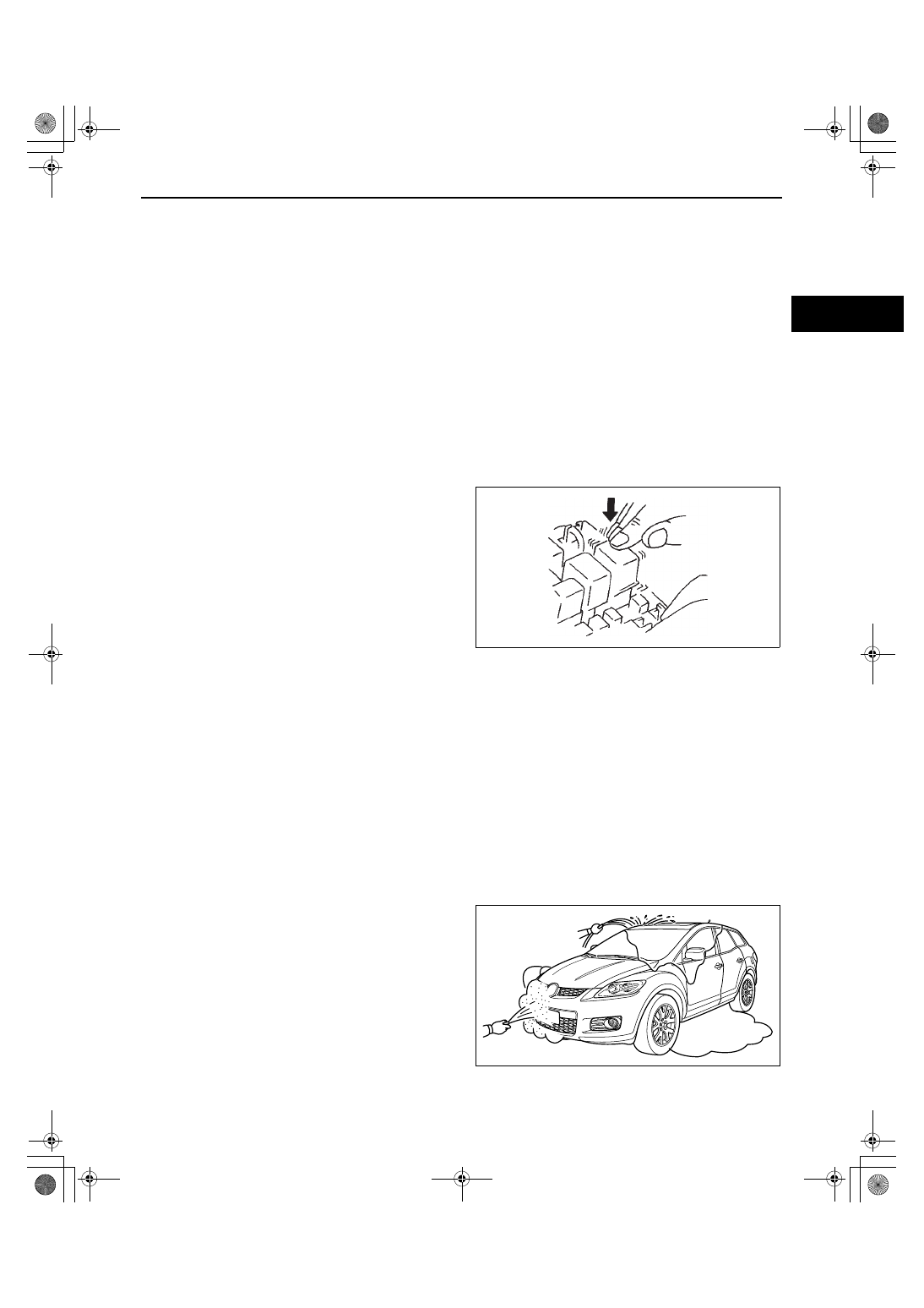
5. Spray water onto the vehicle or run it through a 

car wash.

• If the PID value is unstable or a malfunction 

occurs, repair or replace parts if necessary.

End Of Sie

acxuuw00002368

acxuuw00001941

1871-1U-06B(01-03).fm  77 ページ  2006年3月15日 水曜日 午前10時36分

SYMPTOM TROUBLESHOOTING [L3 WITH TC]

01-03–78

ENGINE CONTROL SYSTEM OPERATION INSPECTION[L3 WITH TC]

id010339803700

Input Signal System Investigation Procedure

1. Find an unusual signal. (See01-03-78 Finding unusual signals.)
2. Locate the source. (See01-03-78 Locating the source of unusual signals.)
3. Repair or replace the defective part.
4. Confirm that the unusual signal has been erased.

Finding unusual signals
While referring to 01-02-7 ON-BOARD DIAGNOSTIC TEST[L3 WITH TC], use the PID/DATA monitor and record 
function to inspect the input signal system relating to the problem.

1. Start the engine and idle the vehicle. You can assume that any signals that are out of specification by a wide 

margin are unusual.

2. When recreating the problem, any sudden change in the monitor input signals that is not consciously created 

by the driver can be determined as unusual.

Locating the source of unusual signals

Caution

• Compare the M-MDS monitor voltage with the measurement voltage using the digital 

measurement system function. If you use another tester, a misreading may occur.

• When measuring the voltage, attach the tester ground to the ground of the PCM that is being 

tested, or to the engine itself. If this is not done, the measured voltage and actual voltage may 
differ

• After connecting the pin to a waterproof coupler, confirm continuity and measure the voltage, and 

inspect the waterproof connector for cracks. If there are any, use sealant to fix them. Failure to do 
this may result in deterioration of the wiring harness or terminal from water damage, leading to 
problems with the vehicle.

Variable resistance type 1 (TP sensor)

Investigate the input signal system for variable resistance type 1

1. When an unusual signal is received, measure the #1 PCM terminal voltage.

• If the #1 terminal voltage and the M-MDS monitor voltage are the same, proceed to the next step.

• If there is a difference of 0.5 V or more, inspect for the following points concerning the PCM connector:

— Female terminal opening is loose.

— Coupler (pin holder) damage

— Pin discoloration (blackness)

— Wiring harness/pin crimp is loose or disconnected.

2. Measure the #2 sensor terminal voltage.

• If there is a 0.5 V or more difference between the sensor and M-MDS voltages, inspect the wiring harness 

for open or short circuits.

• If the sensor and M-MDS voltages are the same, inspect for the following points concerning the sensor 

connector:

— Female terminal opening is loose.

— Coupler (pin holder) damage

— Pin discoloration (blackness)

• If there are no problems, proceed to next investigation below.

PCM

VREF

INPUT

GND

4

1

6

3

2

5

acxuuw00002364

1871-1U-06B(01-03).fm  78 ページ  2006年3月15日 水曜日 午前10時36分

SYMPTOM TROUBLESHOOTING [L3 WITH TC]

01-03–79

01-03

Investigate the standard power supply system for variable resistance type 1

•  Confirm that the #3 terminal is at 5 V.

— If the measured voltage on the #3 terminal is5 V, inspect the following points on the sensor connector.

— If there is no problem, inspect for the following:

• Female terminal opening loose

• Coupler (pin holder) damage

• Pin discoloration (blackness)

— If the #3 terminal measures other than 5 V, inspect for the following:

• Open or short circuit in wiring harness

• Wiring harness/pin crimp is loose or disconnected.

Investigate the ground system for variable resistance type 1

• Confirm that terminal sensor #5 is at 0 V.

— If it is at0 V, inspect the sensor.

• If necessary, replace the sensor.

— If not, inspect for the following:

• Open or short circuit in wiring harness

• Female terminal opening is loose causing an open or short circuit in wiring harness

• Coupler (pin holder) damage

• Pin discoloration (blackness)

• Wiring harness/pin crimp is loose or disconnected.

Variable resistance type 2 (fuel tank level sensor and mass air flow (MAF) sensor)

Investigate the ground system for variable resistance type 2

• Confirm that terminal sensor #4 is at 0 V.

— If it is at 0 V, inspect the sensor.

• If necessary, replace the sensor.

— If not at 0 V, inspect for the following:

• Open circuit in wiring harness

• Female terminal opening is loose.

• Coupler (pin holder) damage

• Pin discoloration (blackness)

• Wiring harness/pin crimp is loose or disconnected.

Investigate the input signal system for variable resistance type 2

1. When an unusual signal is received, measure the #1 PCM terminal voltage.

• If the #1 terminal voltage and the M-MDS monitor voltage are the same, proceed to the next step.

• If there is a difference of 0.5 V or more, inspect for the following points concerning the PCM connector:

— Female terminal opening is loose.

— Coupler (pin holder) damage

— Pin discoloration (blackness)

— Wiring harness/pin crimp is loose or disconnected.

2. Measure the #2 sensor terminal voltage.

• If there is a 0.5 V or more difference between the sensor and M-MDS voltages, inspect the wiring harness 

for open or short circuits.

• If the sensor and M-MDS voltages are the same, inspect the following points concerning the sensor 

connector:

— Female terminal opening is loose.

— Coupler (pin holder) damage

— Pin discoloration (blackness)

— Wiring harness/pin crimp is loose or disconnected.

• If there are no problems, proceed to next investigation below.

PCM

INPUT

GND

4

1

3

2

5

acxuuw00002365

1871-1U-06B(01-03).fm  79 ページ  2006年3月15日 水曜日 午前10時36分

SYMPTOM TROUBLESHOOTING [L3 WITH TC]

01-03–80

Investigate the electrical supply system for variable resistance type 2

• Confirm that the sensor #3 terminal is B+.

— If the measured voltage on the #3 terminal is B+, inspect the following points on the sensor connector.

— If there is no problem, inspect for the following:

• Female terminal opening is loose.

• Coupler (pin holder) damage

• Pin discoloration (blackness)

— If the #3 terminal measures other than B+, inspect the following:

• Open or short circuit in wiring harness

• Wiring harness/pin crimp is loose or disconnected.

Thermistor type (IAT sensor and ECT sensor)

Investigate the input signal system for thermistor type

1. When an unusual signal is received, measure the #1 PCM terminal voltage.

• If the #1 terminal voltage and the M-MDS monitor voltage are the same, proceed to the next step.

• If there is a difference of 0.5 V or more, inspect the following points concerning the PCM connector:

— Female terminal opening loose

— Coupler (pin holder) damage

— Pin discoloration (blackness)

— Wiring harness/pin crimp is loose or disconnected.

2. Measure the #2 sensor terminal voltage.

• If there is a 0.5 V or more difference between the sensor and M-MDS voltages, inspect the wiring harness 

for open or short circuits.

• If the sensor and M-MDS voltages are the same, inspect the following points concerning the sensor 

connector:

— Female terminal opening is loose.

— Coupler (pin holder) damage

— Pin discoloration (blackness)

— Wiring harness/pin crimp is loose or disconnected.

• If there are no problems, proceed to next investigation below.

Investigate the ground system for thermistor type

• Confirm that terminal sensor #3 is at 0 V.

— If it is at 0 V, inspect the sensor. If necessary, replace the sensor.

— If not, inspect for the following:

• Open circuit in wiring harness

• Female terminal opening is loose.

• Coupler (pin holder) damage

• Pin discoloration (blackness)

• Wiring harness/pin crimp is loose or disconnected.

PCM

INPUT

GND

4

1

3

2

acxuuw00002366

1871-1U-06B(01-03).fm  80 ページ  2006年3月15日 水曜日 午前10時36分


Content   ..  93  94  95  96   ..