Mazda CX 7. Manual - part 56
ON-BOARD DIAGNOSTIC [L3 WITH TC]
01-02–179
01-02
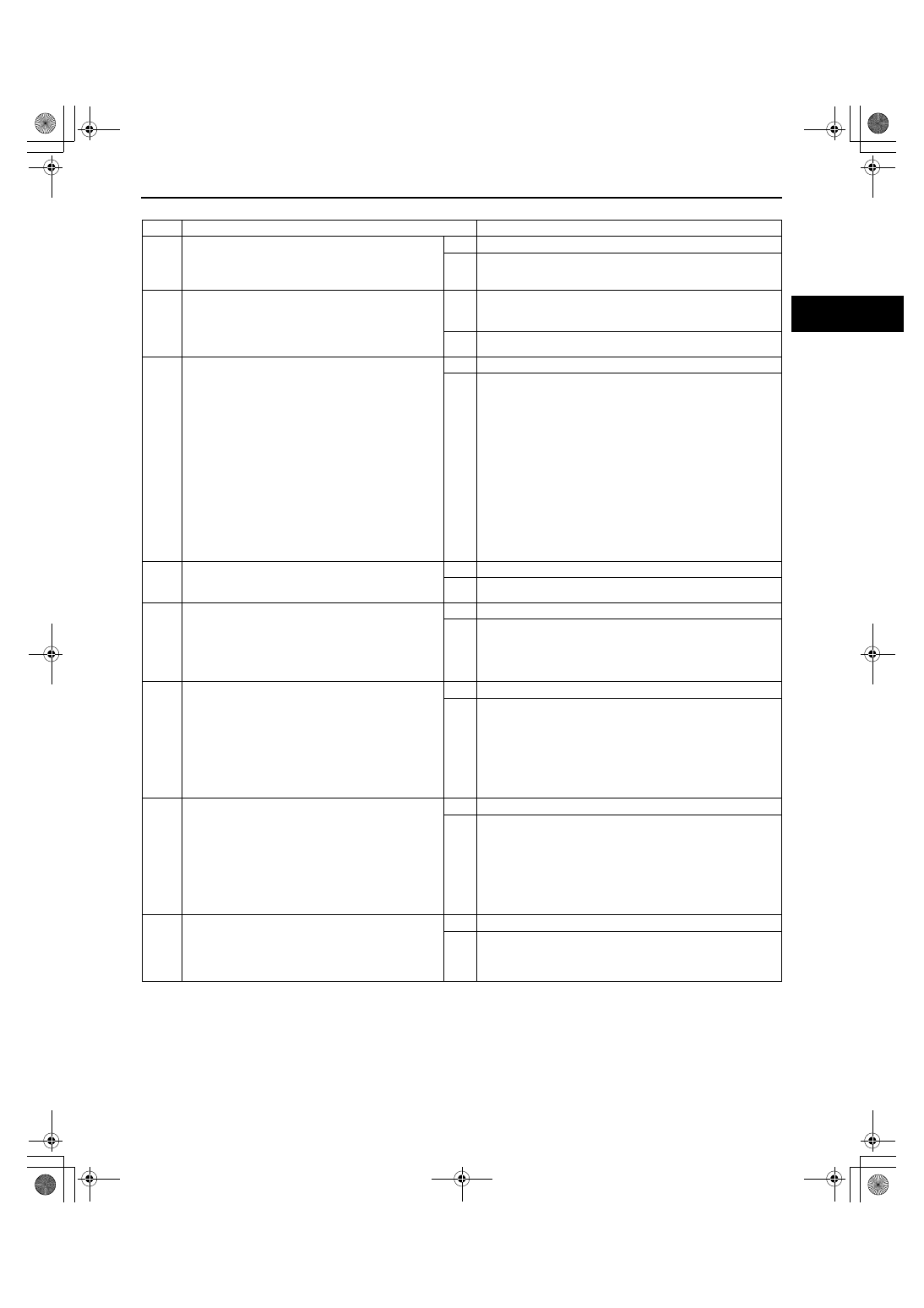
Diagnostic procedure
STEP
INSPECTION
ACTION
1
VERIFY FREEZE FRAME DATA HAS BEEN
RECORDED
• Has the FREEZE FRAME DATA been
recorded?
Yes
Go to the next step.
No
Record FREEZE FRAME DATA on the repair order, then go
to the next step.
2
VERIFY RELATED REPAIR INFORMATION
AVAILABILITY
• Check for related Service Bulletins and/or on-
line repair information availability.
• Is any related repair information available?
Yes
Perform the repair or diagnosis according to the available
repair information.
• If the vehicle is not repaired, go to the next step.
No
Go to the next step.
3
CLASSIFY INTERMITTENT CONCERN OR
CONTINUOUS CONCERN
• Clear the DTC from the PCM memory using
the M-MDS.
• Drive the vehicle under the following
conditions:
— Engine coolant temperature is above 63
°C
{145
°F}.
— Engine speed: below 3,750 rpm
— Throttle opening angle is as follows:
• Engine speed below 1,500 rpm: above
35%
• Engine speed between 1,500— 2,500
rpm: between 25— 35%
• Engine speed above 2,500: below 25%
• Is the PENDING CODE for this DTC present?
Yes
Go to the next step.
No
Intermittent concern exists. Go to INTERMITTENT
CONCERN TROUBLESHOOTING procedure.
(See01-03-76 INTERMITTENT CONCERN
TROUBLESHOOTING[L3 WITH TC].)
4
VERIFY IF STORED OTHER DTCs STORED
• Verify stored DTCs using the M-MDS.
• Is DTC P2088 or P2089 present?
Yes
Go to the appropriate DTC troubleshooting procedures.
No
Go to the next step.
5
INSPECT VARIABLE SWIRL SOLENOID VALVE
• Perform “VARIABLE SWIRL SOLENOID
VALVE INSPECTION”.
(See01-13-13 VARIABLE SWIRL SOLENOID
VALVE INSPECTION[L3 WITH TC].)
• Is the variable swirl solenoid valve normal?
Yes
Go to the next step.
No
Replace variable swirl solenoid valve, then go to Step 13.
6
INSPECT VARIABLE SWIRL SHUTTER VALVE
ACTUATOR
• Perform “VARIABLE SWIRL SHUTTER VALVE
ACTUATOR INSPECTION”.
(See01-13-13 VARIABLE SWIRL SHUTTER
VALVE ACTUATOR INSPECTION[L3 WITH
TC].)
• Is the variable swirl shutter valve actuator
normal?
Yes
Go to the next step.
No
Replace the intake manifold, then go to Step 13.
7
INSPECT VARIABLE SWIRL SHUTTER VALVE
SWITCH
• Perform the “VARIABLE SWIRL SHUTTER
VALVE SWITCH INSPECTION”.
(See01-13-13 VARIABLE SWIRL SHUTTER
VALVE ACTUATOR INSPECTION[L3 WITH
TC].)
• Is the variable swirl shutter valve switch
normal?
Yes
Go to the next step.
No
Replace the intake manifold, then go to Step 13.
8
VERIFY CONNECTION OF VACUUM HOSE
ROUTING
• Verify that the vacuum hoses are connected
properly.
• Are the vacuum hoses connected properly?
Yes
Go to the next step.
No
Connect the vacuum hoses properly, then go to the next
step.
1871-1U-06B(01-02).fm 179 ページ 2006年3月15日 水曜日 午前10時32分