Mazda CX 7. Manual - part 36
ON-BOARD DIAGNOSTIC [L3 WITH TC]
01-02–99
01-02
Diagnostic procedure
STEP
INSPECTION
ACTION
1
VERIFY FREEZE FRAME DATA HAS BEEN
RECORDED
• Has the FREEZE FRAME DATA been
recorded?
Yes
Go to the next step.
No
Record the FREEZE FRAME DATA on the repair order,
then go to the next step.
2
VERIFY RELATED REPAIR INFORMATION
AVAILABILITY
• Verify related Service Bulletins and/or on-line
repair information availability.
• Is any related repair information available?
Yes
Perform the repair or diagnosis according to the available
repair information.
• If the vehicle is not repaired, go to the next step.
No
Go to the next step.
3
INSPECT FUEL INJECTOR NO.1 CONNECTOR
FOR POOR CONNECTION
• Turn the ignition switch off.
• Disconnect the fuel injector No.1 connector.
• Inspect for poor connection (such as damaged/
pulled-out pins, corrosion).
• Is there any malfunction?
Yes
Repair or replace the terminal, then go to Step 10.
No
Go to the next step.
4
INSPECT FUEL INJECTOR NO.1 CIRCUIT FOR
SHORT TO GROUND
• Turn the ignition switch off.
• Inspect for continuity between the following
terminals:
— Fuel injector No.1 terminal B (wiring
harness-side) and body ground
— Fuel injector No.1 terminal A (wiring
harness-side) and body ground
• Is there continuity?
Yes
Repair or replace the wiring harness for a possible short to
ground, then go to Step 10.
No
Go to the next step.
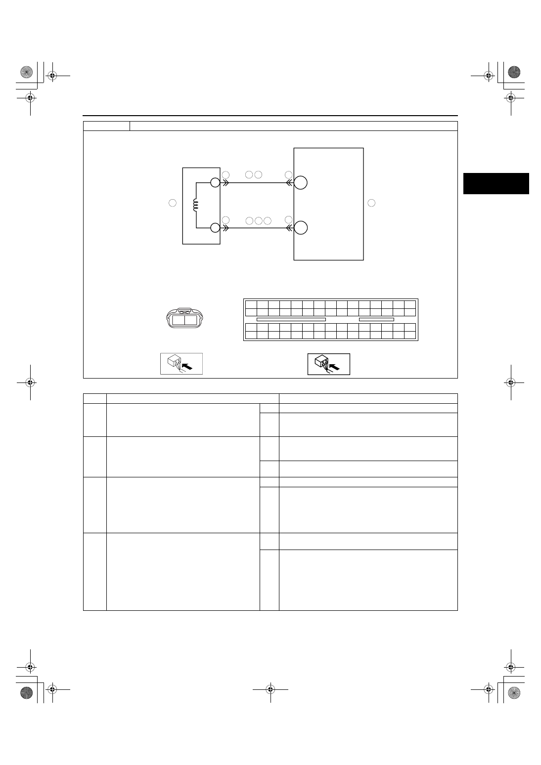
DTC P0201
Injector circuit/open cylinder No.1
B
A
PCM
9
6
8
3
8
2BB
FUEL INJECTOR
NO.1
WIRING HARNESS-SIDE CONNECTOR
A
B
9
4
FUEL INJECTOR NO.1
2BG
3
5
4
7
PCM
WIRING HARNESS-SIDE CONNECTOR
2BE 2BA 2AW 2AS 2AO 2AK 2AG 2AC 2Y 2U 2Q 2M
2E
2A
2I
2BH 2BD 2AZ 2AV 2AR 2AN 2AJ 2AF 2AB 2X 2T 2P
2H
2D
2L
2BG 2BC 2AY 2AU 2AQ 2AM 2AI 2AE 2AA 2W 2S 2O
2G
2C
2K
2BF 2BB 2AX 2AT 2AP 2AL 2AH 2AD 2Z
2V 2R 2N
2F
2B
2J
1871-1U-06B(01-02).fm 99 ページ 2006年3月15日 水曜日 午前10時32分