Mazda CX 7. Manual - part 23
ON-BOARD DIAGNOSTIC [L3 WITH TC]
01-02–47
01-02
End Of Sie
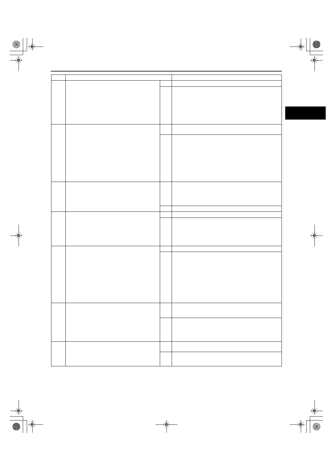
WM: DTC P01XX
3
INSPECT MAP/BOOST AIR TEMPERATURE
SENSOR CONNECTOR FOR POOR
CONNECTION
• Turn the ignition switch off.
• Disconnect the MAP/boost air temperature
sensor connector.
• Inspect for poor connection (damaged, pulled-
out pins, corrosion, etc.).
• Is there any malfunction?
Yes
Repair or replace the terminal, then go to Step 8.
No
Go to the next step.
4
INSPECT MAP/BOOST AIR TEMPERATURE
SENSOR CIRCUIT FOR SHORT TO POWER
SUPPLY
• Turn the ignition switch to the ON position
(Engine off).
• Measure the voltage between the following
terminals:
— MAP/boost air temperature sensor terminal
B (wiring harness-side) and body ground
— MAP/boost air temperature sensor terminal
A (wiring harness-side) and body ground
• Is the voltage B+?
Yes
Repair or replace the wiring harness for a possible short to
power supply, then go to Step 8.
No
Go to the next step.
5
INSPECT BOOST AIR TEMPERATURE SENSOR
• Inspect the boost air temperature sensor
connector.
(See01-40-31 BOOST AIR TEMPERATURE
SENSOR INSPECTION[L3 WITH TC].)
• Is there any malfunction?
Yes
Replace the MAP/boost air temperature sensor, then go to
Step 8.
(See01-40-29 MANIFOLD ABSOLUTE PRESSURE (MAP)
SENSOR/BOOST AIR TEMPERATURE SENSOR
REMOVAL/INSTALLATION[L3 WITH TC].)
No
Go to the next step.
6
INSPECT PCM CONNECTOR FOR POOR
CONNECTION
• Turn the ignition switch off.
• Disconnect the PCM connector.
• Inspect for poor connection (damaged, pulled-
out pins, corrosion, etc.).
• Is there any malfunction?
Yes
Repair or replace the terminal, then go to Step 8.
No
Go to the next step.
7
INSPECT MAP/BOOST AIR TEMPERATURE
SENSOR CIRCUIT FOR OPEN CIRCUIT
• Turn the ignition switch off.
• Measure the voltage between the following
terminals:
— MAP/boost air temperature sensor terminal
B (wiring harness-side) and PCM terminal
2N (wiring harness-side)
— MAP/boost air temperature sensor terminal
A (wiring harness-side) and PCM terminal
2AV (wiring harness-side)
• Is there continuity?
Yes
Go to the next step.
No
Repair or replace the wiring harness for a possible open
circuit, then go to the next step.
8
VERIFY TROUBLESHOOTING OF DTC P0098
COMPLETED
• Make sure to connect all disconnected
connectors.
• Clear the DTC from the PCM memory using
the M-MDS.
• Start the engine.
• Is the same DTC present?
Yes
Replace the PCM, then go to the next step.
(See01-40-6 PCM REMOVAL/INSTALLATION[L3 WITH
TC].)
No
Go to the next step.
9
VERIFY AFTER REPAIR PROCEDURE
• Perform the “AFTER REPAIR PROCEDURE”.
(See01-02-10 AFTER REPAIR
PROCEDURE[L3 WITH TC].)
• Are any DTCs present?
Yes
Go to the applicable DTC inspection.
(See01-02-13 DTC TABLE[L3 WITH TC].)
No
DTC troubleshooting completed.
STEP
INSPECTION
ACTION
1871-1U-06B(01-02).fm 47 ページ 2006年3月15日 水曜日 午前10時32分