Mazda CX 7. Manual - part 21
ON-BOARD DIAGNOSTIC [L3 WITH TC]
01-02–39
01-02
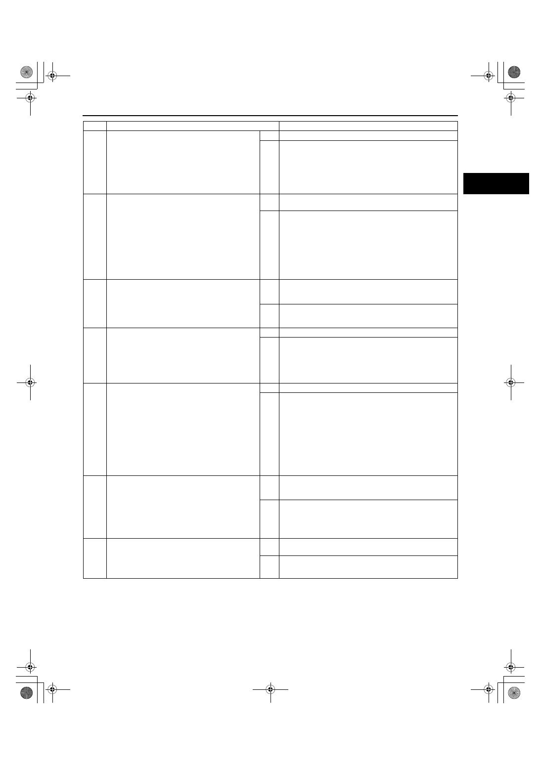
End Of Sie
3
INSPECT HIGH PRESSURE FUEL PUMP
CONNECTOR FOR POOR CONNECTION
• Turn the ignition switch off.
• Disconnect the high pressure fuel pump
connector.
• Inspect for poor connection (such as damaged/
pulled-out pins, corrosion).
• Is there any malfunction?
Yes
Repair or replace the terminal, then go to Step 8.
No
Go to the next step.
4
INSPECT SPILL VALVE CONTROL SOLENOID
VALVE CONTROL CIRCUIT FOR SHORT TO
GROUND
• Turn the ignition switch off.
• Inspect for continuity between the following
terminals:
— High pressure fuel pump terminal A (wiring
harness-side) and body ground
— High pressure fuel pump terminal B (wiring
harness-side) and body ground
• Is there continuity?
Yes
Repair or replace the wiring harness for a possible short to
ground, then go to Step 8.
No
Go to the next step.
5
INSPECT SPILL VALVE CONTROL SOLENOID
VALVE
• Inspect the spill valve control solenoid valve.
(See01-14-19 HIGH PRESSURE FUEL
PUMP INSPECTION[L3 WITH TC].)
• Is there any malfunction.
Yes
Replace the high pressure fuel pump, then go to Step 8.
(See01-14-16 HIGH PRESSURE FUEL PUMP REMOVAL/
INSTALLATION[L3 WITH TC].)
No
Go to the next step.
6
INSPECT PCM CONNECTOR FOR POOR
CONNECTION
• Turn the ignition switch off.
• Disconnect the PCM connector.
• Inspect for poor connection (such as damaged/
pulled-out pins, corrosion).
• Is there any malfunction?
Yes
Repair or replace the terminal, then go to Step 8.
No
Go to the next step.
7
INSPECT SPILL VALVE CONTROL SOLENOID
VALVE CONTROL CIRCUIT FOR OPEN CIRCUIT
• Turn the ignition switch off.
• Inspect for continuity between the following
terminals:
— High pressure fuel pump terminal A (wiring
harness-side) and PCM terminal 2F (wiring
harness-side)
— High pressure fuel pump terminal B (wiring
harness-side) and PCM terminal 2G (wiring
harness-side)
• Is there continuity?
Yes
Go to the next step.
No
Repair or replace the wiring harness for a possible open
circuit, then go to the next step.
8
VERIFY TROUBLESHOOTING OF DTC P0091
COMPLETED
• Make sure to reconnect all the disconnected
connectors.
• Clear the DTC from the PCM memory using
the M-MDS.
• Start the engine.
• Is the same DTC present?
Yes
Replace the PCM, then go to the next step.
(See01-40-6 PCM REMOVAL/INSTALLATION[L3 WITH
TC].)
No
Go to the next step.
9
VERIFY AFTER REPAIR PROCEDURE
• Perform the “AFTER REPAIR PROCEDURE”.
(See01-02-10 AFTER REPAIR
PROCEDURE[L3 WITH TC].)
• Are any DTCs present?
Yes
Go to the applicable DTC inspection.
(See01-02-13 DTC TABLE[L3 WITH TC].)
No
DTC troubleshooting completed.
STEP
INSPECTION
ACTION
1871-1U-06B(01-02).fm 39 ページ 2006年3月15日 水曜日 午前10時32分