Mazda CX 7. Manual - part 17


  Index      Mazda     Mazda CX 7 - service repair manual 2007 year


Search            


Content   ..  15  16  17  18   ..


Mazda CX 7. Manual - part 17


ON-BOARD DIAGNOSTIC [L3 WITH TC]

01-02–23

01-02

End Of Sie

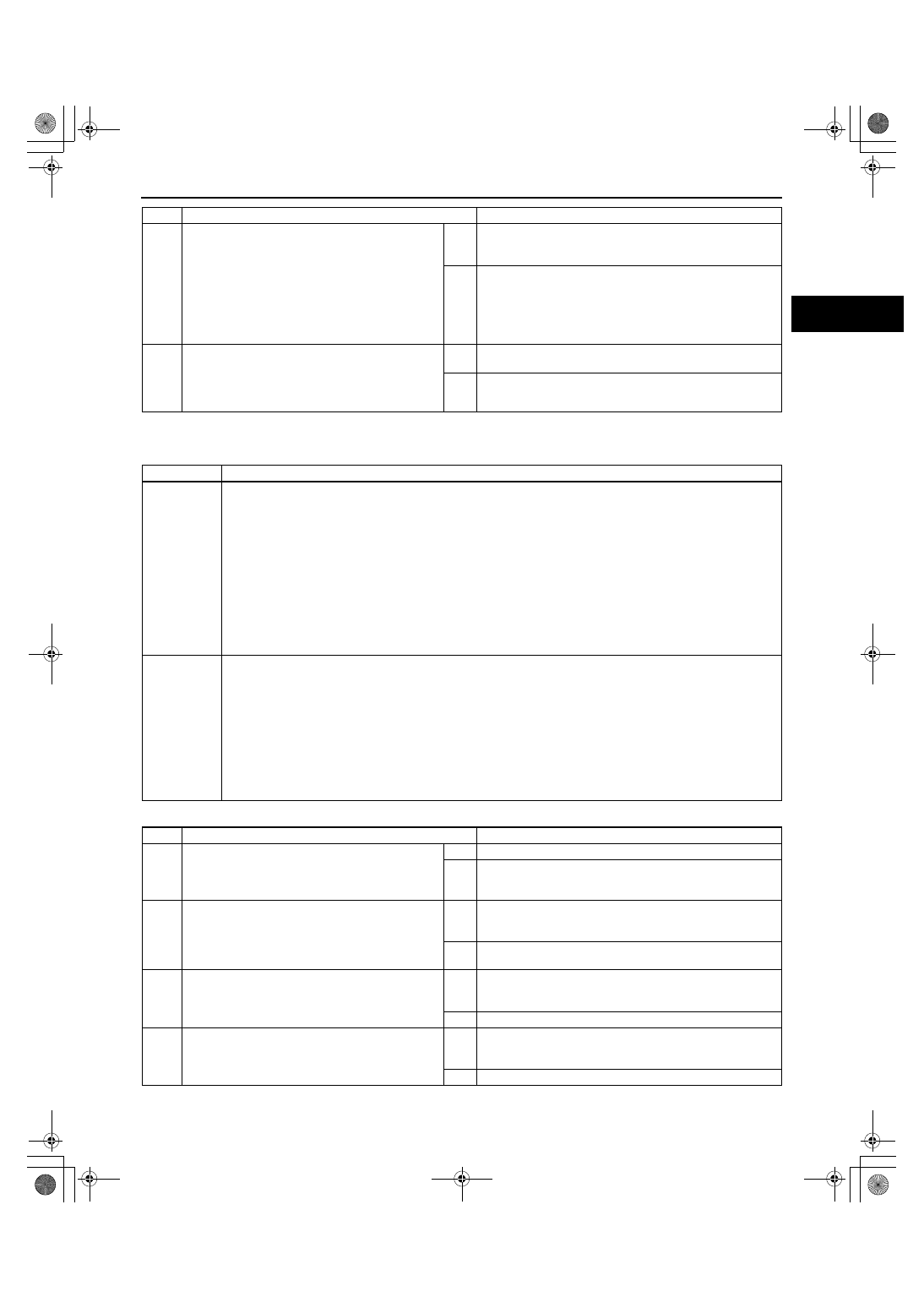
DTC P0012[L3 WITH TC]

id010239801700

Diagnostic procedure

7

VERIFY TROUBLESHOOTING OF DTC P0011 
COMPLETED

• Make sure to reconnect all the disconnected 

connectors.

• Clear the DTC from the PCM memory using 

the M-MDS.

• Turn the ignition switch off.

• Start the engine and warm it up completely.

• Is PENDING CODE for this DTC present?

Yes

Replace the PCM, then go to the next step.
 (See 01-40-6 PCM REMOVAL/INSTALLATION[L3 WITH 
TC].)

No

Go to the next step.

8

VERIFY AFTER REPAIR PROCEDURE

• Perform the “After Repair Procedure”.

 (See 01-02-10 AFTER REPAIR 
PROCEDURE[L3 WITH TC].)

• Are any DTCs present?

Yes

Go to the applicable DTC inspection.
 (See 01-02-13 DTC TABLE[L3 WITH TC].)

No

Troubleshooting completed.

STEP

INSPECTION

ACTION

DTC P0012

CMP Timing over-retarded

DETECTION 

CONDITION

• Actual valve timing is over-retarded by ° (when the following conditions are met) from the target 

valve timing for 5 s when the OCV system control is within the feed-back range.

MONITORING CONDITION

— Engine speed is below 4,000 rpm.

— Engine coolant temperature is above 70— 110 

°C {158— 230 °F}.

Diagnostic support note

• This is a continuous monitor (CCM).

• MIL illuminates if the PCM detects the above malfunction condition in two consecutive drive cycles or in 

one drive cycle while the DTC for the same malfunction has been stored in the PCM.

• PENDING CODE is available if the PCM detects the above malfunction condition during the first drive 

cycle.

• FREEZE FRAME DATA is available.

• DTCs are stored in the PCM memory.

POSSIBLE 

CAUSE

• OCV malfunction

• Low engine oil pressure

• Spool valve in OCV is stuck in the retard position.

• Variable valve timing actuator is stuck in the retard position.

• Following oil runners are clogged or have leakage.

Oil runners

• Between oil pressure switch and OCV

• Between OCV and variable valve timing actuator

• In variable valve timing actuator

• Loose timing chain or improper valve timing due to timing chain slippage

• PCM malfunction

STEP

INSPECTION

ACTION

1

VERIFY FREEZE FRAME DATA HAS BEEN 
RECORDED

• Has the FREEZE FRAME DATA been 

recorded?

Yes

Go to the next step.

No

Record FREEZE FRAME DATA on the repair order, then go 
to the next step.

2

VERIFY RELATED REPAIR INFORMATION 
AVAILABILITY

• Check for related Service Bulletins and/or on-

line repair information availability.

• Is any related repair information available?

Yes

Perform the repair or diagnosis according to the available 
repair information.

• If the vehicle is not repaired, go to the next step.

No

Go to the next step.

3

VERIFY RELATED PENDING CODE OR 
STORED DTCS

• Is DTC P2088 or P2089 present?

Yes

Go to the appropriate DTC troubleshooting procedure.
 (See 01-02-188 DTC P2088[L3 WITH TC] or 01-02-190 
DTC P2089[L3 WITH TC].)

No

Go to the next step.

4

VERIFY ENGINE OIL PRESSURE

• Start the engine.

• Does the oil pressure warning light illuminate?

Yes

Inspect engine oil pressure.
 (See 01-11-2 OIL PRESSURE INSPECTION[L3 WITH 
TC].)

No

Go to the next step.

1871-1U-06B(01-02).fm  23 ページ  2006年3月15日 水曜日 午前10時32分

ON-BOARD DIAGNOSTIC [L3 WITH TC]

01-02–24

End Of Sie

5

VERIFY TIMING CHAIN INSTALLATION

• Stop the engine.

• Remove the timing chain cover.

• Is the camshaft timing mark at the correct 

point?
 (See 01-10-10 TIMING CHAIN REMOVAL/
INSTALLATION[L3 WITH TC].)

Yes

Go to the next step.

No

Reinstall the timing chain, then go to Step 8.

6

INSPECT OCV FOR MALFUNCTION

• Stop the engine.

• Remove the OCV.

• Inspect the position of the spool valve in the 

OCV.

• Is the spool valve located at the valve retard 

position?

Yes

VARIABLE VALVE TIMING MECHANISM IS NORMAL

Note

• This DTC is detected as an intermittent concern.

• The intermittent concern might be removed using the 

cleaning mode of the variable valve timing control 
function.

Go to the next step.

No

Replace the OCV, then go to Step 8.

7

INSPECT ENGINE OIL RUNNER

• Inspect the following engine oil runners for 

clogging or leakage.

— Between the oil pressure switch and the 

OCV 

— Between the OCV and the variable valve 

timing actuator

— In the variable valve timing actuator

• Is there any clogging or leakage?

Yes

Repair or replace the suspected runner, then go to the next 
step.

No

VARIABLE VALVE TIMING MECHANISM IS NORMAL

Note

• This DTC is detected as an intermittent concern.

• The intermittent concern might be removed using the 

cleaning mode of the variable valve timing control 
function.

Go to the next step.

8

VERIFY TROUBLESHOOTING OF DTC P0012 
COMPLETED

• Make sure to reconnect all disconnected 

connectors.

• Clear the DTC from the PCM memory using 

the M-MDS.

• Turn the ignition switch off.

• Start the engine and warm it up completely.

• Is PENDING CODE for this DTC present?

Yes

Replace the PCM, then go to the next step.
 (See 01-40-6 PCM REMOVAL/INSTALLATION[L3 WITH 
TC].)

No

Go to the next step.

9

VERIFY AFTER REPAIR PROCEDURE

• Perform the “After Repair Procedure”.

 (See 01-02-10 AFTER REPAIR 
PROCEDURE[L3 WITH TC].)

• Are any DTCs present?

Yes

Go to the applicable DTC inspection.
 (See 01-02-13 DTC TABLE[L3 WITH TC].)

No

Troubleshooting completed.

STEP

INSPECTION

ACTION

1871-1U-06B(01-02).fm  24 ページ  2006年3月15日 水曜日 午前10時32分

ON-BOARD DIAGNOSTIC [L3 WITH TC]

01-02–25

01-02

DTC P0016[L3 WITH TC]

id010239801800

Diagnostic procedure

DTC P0016

CKP-CMP correlation

DETECTION 

CONDITION

• The PCM monitors the input pulses from the CKP sensor and CMP sensor. If the input pulse pick-up timing 

do not match each other, the PCM determines that the camshaft position does not coincide with the 
crankshaft position.

Diagnostic support note

• This is a continuous monitor (CCM).

• MIL illuminates if the PCM detects the above malfunction condition in two consecutive drive cycles or in 

one drive cycle while the DTC for the same malfunction has been stored in the PCM.

• PENDING CODE is available if the PCM detects the above malfunction condition during the first drive 

cycle.

• FREEZE FRAME DATA is available.

• DTCs are stored in the PCM memory.

POSSIBLE 

CAUSE

• Poor connection of connector

• CMP sensor malfunction

• CKP sensor malfunction

• Damaged or scratched CMP sensor pulse wheel

• Damaged or scratched CKP sensor pulse wheel

• Foreign material on CMP sensor

• Foreign material on CKP sensor

• Improper valve timing

STEP

INSPECTION

ACTION

1

VERIFY FREEZE FRAME DATA HAS BEEN 
RECORDED

• Has the FREEZE FRAME DATA been 

recorded?

Yes

Go to the next step.

No

Record the FREEZE FRAME DATA on the repair order, 
then go to the next step.

2

VERIFY RELATED REPAIR INFORMATION 
AVAILABILITY

• Verify related Service Bulletins and/or on-line 

repair information availability.

• Is any related repair information available?

Yes

Perform the repair or diagnosis according to the available 
repair information.

• If the vehicle is not repaired, go to the next step.

No

Go to the next step.

3

INSPECT CMP SENSOR CONNECTOR FOR 
POOR CONNECTION

• Turn the ignition switch off.

• Disconnect the CMP sensor connector.

• Inspect for poor connection (such as damaged/

pulled-out pins, corrosion).

• Is there any malfunction?

Yes

Repair or replace the terminal, then go to Step 13.

No

Go to the next step.

4

INSPECT CMP SENSOR FOR FOREIGN 
MATERIAL

• Remove the CMP sensor.

• Inspect the CMP sensor for foreign material.

• Is there any foreign material on the CMP 

sensor?

Yes

Remove foreign material from the CMP sensor, then go to 
Step 13.

No

Go to the next step.

5

INSPECT CMP SENSOR PULSE WHEEL

• Visually inspect the CMP sensor pulse wheel.

• Is there any damage or scratching to the CMP 

sensor pulse wheel?

Yes

Replace the camshaft, then go to Step 13.
(See01-10-20 CYLINDER HEAD GASKET 
REPLACEMENT[L3 WITH TC].)

No

Go to the next step.

6

INSPECT CMP SENSOR

• Inspect the CMP sensor.

(See01-40-45 CAMSHAFT POSITION (CMP) 
SENSOR INSPECTION[L3 WITH TC].)

• Is the CMP sensor normal?

Yes

Go to the next step.

No

Replace the CMP, then go to Step 13.

7

INSPECT CKP SENSOR CONNECTOR FOR 
POOR CONNECTION

• Turn the ignition switch off.

• Disconnect the CKP sensor connector.

• Inspect for poor connection (such as damaged/

pulled-out pins, corrosion).

• Is there any malfunction?

Yes

Repair or replace the terminal, then go to Step 13.

No

Go to the next step.

1871-1U-06B(01-02).fm  25 ページ  2006年3月15日 水曜日 午前10時32分

ON-BOARD DIAGNOSTIC [L3 WITH TC]

01-02–26

End Of Sie

DTC P0030[L3 WITH TC]

id010239801900

8

INSPECT CKP SENSOR FOR FOREIGN 
MATERIAL

• Remove the CKP sensor.

• Inspect the CKP sensor for foreign material.

• Is there any foreign material on the CKP 

sensor?

Yes

Remove foreign material from the CKP sensor, then go to 
Step 13.

No

Go to the next step.

9

INSPECT CKP SENSOR PULSE WHEEL

• Visually inspect the CKP sensor pulse wheel.

• Is there any damage or scratching to the CKP 

sensor pulse wheel?

Yes

Replace the CKP sensor pulse wheel, then go to Step 13. 
(See01-10-10 TIMING CHAIN REMOVAL/
INSTALLATION[L3 WITH TC].)

No

Go to the next step.

10

INSPECT CKP SENSOR

• Inspect the CKP sensor.

 (See01-40-43 CRANKSHAFT POSITION 
(CKP) SENSOR INSPECTION[L3 WITH TC].)

• Is the CKP sensor normal?

Yes

Go to the next step.

No

Replace the CKP sensor, then go to Step 13.
(See01-40-42 CRANKSHAFT POSITION (CKP) SENSOR 
REMOVAL/INSTALLATION[L3 WITH TC].)

11

INSPECT PCM CONNECTOR FOR POOR 
CONNECTION

• Turn the ignition switch off.

• Disconnect the PCM sensor connector.

• Inspect for poor connection (such as damaged/

pulled-out pins, corrosion).

• Is there any malfunction?

Yes

Repair or replace the terminal, then go to Step 13.

No

Go to the next step.

12

INSPECT VALVE TIMING

• Inspect valve timing.

(See01-10-10 TIMING CHAIN REMOVAL/
INSTALLATION[L3 WITH TC].)

• Is valve timing normal?

Yes

Go to the next step.

No

Adjust the valve timing properly, then go to the next step. 
(See01-10-10 TIMING CHAIN REMOVAL/
INSTALLATION[L3 WITH TC].)

13

VERIFY TROUBLESHOOTING OF DTC P0016 
COMPLETED

• Make sure to reconnect all disconnected 

connectors.

• Turn the ignition switch to the ON position.

• Clear the DTC from the PCM memory using 

the M-MDS.

• Start the engine.

• Is the same DTC present?

Yes

Replace the PCM, then go to the next step.
(See01-40-6 PCM REMOVAL/INSTALLATION[L3 WITH 
TC].)

No

Go to the next step.

14

VERIFY AFTER REPAIR PROCEDURE

• Perform “AFTER REPAIR PROCEDURE”.

(See01-02-10 AFTER REPAIR 
PROCEDURE[L3 WITH TC].)

• Are any DTCs present?

Yes

Go to the applicable DTC inspection.
(See01-02-13 DTC TABLE[L3 WITH TC].)

No

DTC troubleshooting completed.

STEP

INSPECTION

ACTION

DTC P0030

Front HO2S heater control circuit problem

DETECTION 

CONDITION

• OBD system monitors the output signal voltage from oxygen sensor which is in proportion to the element 

impedance of oxygen sensor. If the output signal voltage is not between 0.75 V and 1.5 V after specified 
time from engine start, heater performance is considered failed.

Monitoring condition

• 74 s elapsed from engine start

• Battery voltage:10— 18 V

Diagnostic support note

• This is an intermittent monitor (HO2S heater).

• The MIL illuminates if the PCM detects the above malfunction condition in two consecutive drive cycles or 

in one drive cycle while the DTC for the same malfunction has been stored in the PCM.

• PENDING CODE is available if the PCM detects the above malfunction condition during the first drive 

cycle.

• FREEZE FRAME DATA is available.

• DTCs are stored in the PCM memory.

1871-1U-06B(01-02).fm  26 ページ  2006年3月15日 水曜日 午前10時32分


Content   ..  15  16  17  18   ..