Mazda Protege 5. Manual - part 352


  Index      Mazda     Mazda Protege 5 - service repair manual 2002 year


Search            


Content   ..  350  351  352  353   ..


Mazda Protege 5. Manual - part 352


INSTRUMENTATION/DRIVER INFO. 

09–22–2

End Of Sie

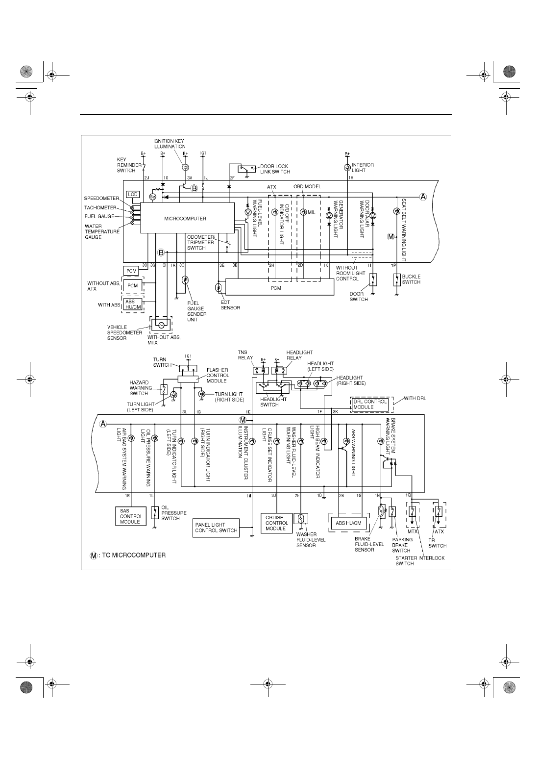
INSTRUMENT CLUSTER SYSTEM WIRING DIAGRAM

A3U092255430W01

End Of Sie

Z3U0922W005

1712-1U-01G(09-22).fm  2 ページ  2001年6月29日 金曜日 午前10時39分

INSTRUMENTATION/DRIVER INFO. 

09–22–3

09–22

INSTRUMENT CLUSTER REMOVAL/INSTALLATION

A3U092255430W02

1. Disconnect the negative battery cable.
2. Pull down the adjusting lever of the tilt steering wheel and push the steering wheel down.
3. Remove the meter hood.
4. Remove in the order indicated in the table.

5. Install in the reverse order of removal.

Instrument Cluster Removal Note

1. When removing the instrument cluster, in order to 

prevent damage to the lens, cover the steering 
shaft with a cloth.

End Of Sie

INSTRUMENT CLUSTER DISASSEMBLY/ASSEMBLY

A3U092255430W03

Caution

••••

If the instrument cluster is dropped or the print plate is damaged, the system will not operate 
properly and it may become the cause of trouble or malfunctions.

1. Disassemble in the order indicated in the table.

2. Assemble in the reverse order of disassembly.

End Of Sie

1

Screw

2

Connector

3

Instrument cluster
(See 09–22–3 Instrument Cluster Removal Note)

X3U922WA0

X3U922WA1

1

Screw

2

Bracket

3

Lens

4

Bulb

5

Screw

6

Cover

7

Screw

8

Instrument cluster

9

Case

Z3U0922W001

1712-1U-01G(09-22).fm  3 ページ  2001年6月29日 金曜日 午前10時39分

INSTRUMENTATION/DRIVER INFO. 

09–22–4

INSTRUMENT CLUSTER INSPECTION

A3U092255430W04

Speedometer

1. Inspect the speedometer by setting it in the input/output check mode DTC 12. (See 09–22–5 INSTRUMENT 

CLUSTER INPUT/OUTPUT CHECK MODE.)

Tachometer

1. Inspect the tachometer by setting it in the input/output check mode DTC 13. (See 09–22–5 INSTRUMENT 

CLUSTER INPUT/OUTPUT CHECK MODE.)

Fuel Gauge

1. Inspect the fuel gauge by setting it in the input/output check mode DTC 23. (See 09–22–5 INSTRUMENT 

CLUSTER INPUT/OUTPUT CHECK MODE.)

Water Temperature Gauge

1. Inspect the water temperature gauge by setting it in the input/output check mode DTC 25. (See 09–22–5 

INSTRUMENT CLUSTER INPUT/OUTPUT CHECK MODE.)

End Of Sie

INSTRUMENT CLUSTER REPAIR

A3U092255430W05

Tachometer

Note

The tach needle will not return to zero if the engine is turned off while the engine speed is 4,000 rpm or 
higher when the ROOM fuse is not installed. The tach needle will continue to rotate clockwise until it rests 
on the wrong side of the stopper pin. If a customer complains of this concern, inspect the ROOM fuse and 
if necessary, repair according to the following steps.

1. Verify the concern.
2. Verify that the ROOM fuse is installed.

3. Start the engine and increase the engine speed to 

approximately 5,500 rpm or until the needle 
begins to move away from the stopper pin 
(counterclockwise).

4. Decrease the engine speed to idle and turn the 

ignition switch to LOCK position.

5. Verify that the needle returns to zero.

If the needle does not return to zero, remove 
the lens and carefully move the needle by 
hand.

End Of Sie

X3U922WC0

X3U922WC1

X3U922WC2

1712-1U-01G(09-22).fm  4 ページ  2001年6月29日 金曜日 午前10時39分

INSTRUMENTATION/DRIVER INFO. 

09–22–5

09–22

INSTRUMENT CLUSTER INPUT/OUTPUT CHECK MODE

A3U092255430W06

Note

In this mode, it is possible to check the items in the following chart.

DTC Chart

Note

The diagnostic trouble codes are displayed in numerical order. (While performing the inspection, if you 
want to inspect a diagnostic trouble code number which is smaller than the code number you are currently 
inspecting, terminate the check mode then repeat the inspection from the beginning.)

If the speed signal is put into the instrument cluster (the front wheels are rotated) while a code other than 
DTC 10 is displayed, the input/output check mode will be cancelled.

The diagnostic trouble codes can be fast-forwarded by pushing and holding the odometer/tripmeter switch 
for 1 second or more.

DTC

Checking item

Related item

01

Buckle switch

Buckle switch

04

Door switch

Ignition key illumination

Room light control

Power door lock system

Lights-on reminder warning buzzer

05

Door lock-link switch

Room light control

08

TNS relay

Lights-on reminder warning buzzer

Each illumination

10

With ABS

ABS HU/CM (vehicle speed signal)

Without ABS, MTX

Vehicle speedometer sensor (vehicle speed signal)

Without ABS, ATX

PCM (vehicle speed signal)

Speedometer

11

PCM (engine speed signal)

Tachometer

12

Speedometer

Speedometer

13

Tachometer

Tachometer

14

Buzzer

Lights-on reminder warning buzzer

Key reminder warning buzzer

16

Fuel-level warning light

Fuel-level warning light

22

Fuel gauge sender unit

Fuel gauge

23

Fuel gauge

Fuel gauge

24

ECT sensor

Water temperature gauge

25

Water temperature gauge

Water temperature gauge

26

LCD

LCD

27

Interior light

Room light control

31

Key reminder switch

Room light control

Keyless entry system

1712-1U-01G(09-22).fm  5 ページ  2001年6月29日 金曜日 午前10時39分


Content   ..  350  351  352  353   ..