Mazda Protege 5. Manual - part 306


  Index      Mazda     Mazda Protege 5 - service repair manual 2002 year


Search            


Content   ..  304  305  306  307   ..


Mazda Protege 5. Manual - part 306


SYMPTOM TROUBLESHOOTING 

09–03–3

09–03

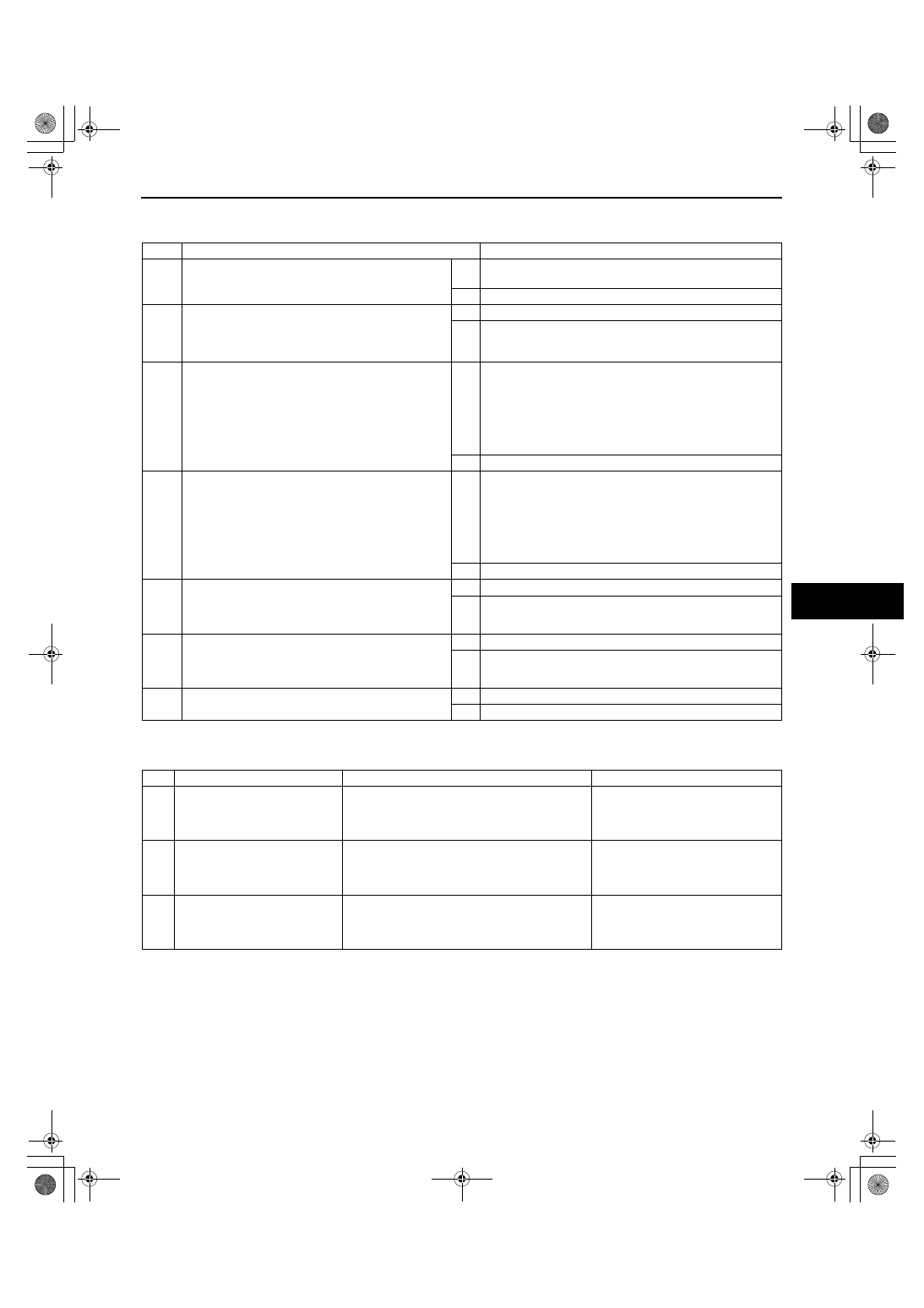
KEYLESS ENTRY SYSTEM PREINSPECTION

A3U090369000W04

1. Perform the following pre-inspection before troubleshooting.

End Of Sie

TROUBLESHOOTING INDEX

A3U090369000W05

End Of Sie

STEP

INSPECTION

ACTION

1

Is the system an after-market one?

Yes Perform troubleshooting according to after-market keyless 

entry system manual.

No

Go to next step.

2

Did customer activate keyless entry system 
when ignition switch was in LOCK position?

Yes Go to next step.

No

Explain to customer that system does not work when 
ignition switch is in ON position.
Turn ignition switch to LOCK position, then go to next step.

3

Did customer use keyless entry system in 
particular area, such as being near TV towers, 
power plants, power lines or factories?

Yes Attempt to lock/unlock doors with transmitter in non-

interference area.

If system operates:
— Area of operation is bad. Explain effect of outside 

interference on transmitter to customer.

If system does not operate:
— Go to next step.

No

Go to next step.

4

Are any of the following after-market electrical 
parts on the vehicle?
— Cellular phone
— Radio-wave equipment
— Remote engine starter
— TV,  etc.

Yes Disconnect after-market electrical part connectors and 

attempt to lock/unlock doors with transmitter.

If system operates:
— After-market electrical parts are interfering with 

keyless entry system.

If system does not operate:
— Go to next step.

No

Go to next step.

5

Perform on-board diagnostic function.
(See 09–02A–2 ON-BOARD DIAGNOSTIC 
FUNCTION [KEYLESS ENTRY SYSTEM])

Does on-board diagnostic function work?

Yes Go to next step.

No

Go to Step 7.

6

Attempt to reprogram keyless control module ID 
code.

Can keyless control module ID code be 
reprogrammed?

Yes System is normal now.

No

Go to Step 1 of troubleshooting No.3.

7

Did any on-board diagnostic functions work?

Yes Go to Step 1 of troubleshooting No.1.

No

Go to Step 1 of troubleshooting No.2.

No.

TROUBLESHOOTING ITEM

DESCRIPTION

PAGE

1

One or more on-board 
diagnostic functions 
inoperative.

Malfunction in horn system, hazard warning 
light system, door lock linkage system, door 
lock switch system or driver’s door key 
cylinder switch system.

(See 09–03–4 NO.1 ONE OR 
MORE ON-BOARD DIAGNOSTIC 
FUNCTIONS INOPERATIVE)

2

All on-board diagnostic 
functions inoperative.

Malfunction in keyless control module power 
supply circuit, door switch circuit, cargo 
compartment light switch circuit (5HB) or 
keyless control module ground circuit.

(See 09–03–6 NO.2 ALL ON-
BOARD DIAGNOSTIC 
FUNCTIONS INOPERATIVE)

3

Transmitter ID code cannot be 
reprogrammed.

Malfunction in transmitter battery, 
transmitter, keyless control module bracket, 
keyless control module bracket ground 
screw or keyless control module circuit.

(See 09–03–7 NO.3 
TRANSMITTER ID CODE CANNOT 
BE REPROGRAMMED)

1712-1U-01G(09-03).fm  3 ページ  2001年6月29日 金曜日 午前10時28分

SYMPTOM TROUBLESHOOTING 

09–03–4

NO.1 ONE OR MORE ON-BOARD DIAGNOSTIC FUNCTIONS INOPERATIVE

A3U090369000W06

When performing an asterisked (*) troubleshooting inspection, shake the wiring harness and connectors while 
performing the inspection to discover whether poor contact points are the cause of any intermittent 
malfunctions. If there is a problem, make sure connectors, terminals and wiring harnesses are connected 
correctly and undamaged.

Diagnostic procedure

1

One or more on-board diagnostic functions inoperative

DESCRIPTION

Malfunction in horn system, hazard light system, door lock linkage system, door lock switch system or 
driver’s door key cylinder switch system.

POSSIBLE 

CAUSE

Malfunction in horn system
— Horn circuit malfunction
— Keyless control module malfunction
— Malfunction in wiring harness between keyless control module and horn relay

Malfunction in hazard light system
— Hazard light circuit
— Keyless control module malfunction
— Malfunction in wiring harness between keyless control module and flasher control module

Malfunction in door lock linkage

Malfunction in door lock switch system

Malfunction in keyless control module door unlock signal circuit
— Keyless control module malfunction
— Malfunction in wiring harness between keyless control module and door lock control module

Malfunction in driver-side door key cylinder switch system

Malfunction in keyless control module door lock/unlock signal circuit
— Keyless control module malfunction
— Malfunction in wiring harness between keyless control module and door lock control module

STEP

INSPECTION

ACTION

1

CHECK HORN, AND HAZARD WARNING LIGHT 
OPERATION DURING ON-BOARD DIAGNOSIS

Did all of the following items work during on-
board diagnostic function operation?
— Horns sounded intermittently
— Hazard warning lights flashed

Yes Go to Step 8.

No

Go to next step.

2

CHECK HORN OPERATION DURING ON-BOARD 
DIAGNOSIS

Did horns sound intermittently during on-board 
diagnostic function operation?

Yes Go to Step 5.

No

Go to next step.

3

INSPECT HORN CIRCUIT

Do horns sound when depressing horn switch on 
vehicle?

Yes Go to next step.

No

Inspect horn circuit.

*4

CHECK TO SEE WHETHER MALFUNCTION IS IN 
WIRING HARNESS (BETWEEN KEYLESS 
CONTROL MODULE AND HORN RELAY) OR 
KEYLESS CONTROL MODULE

Measure voltage at keyless control module 
connector terminal E during on-board diagnostic 
function operation.
— B+

below 1.0 V

B+

below 1.0 V

B+

Is voltage as above?

Yes Recheck malfunction symptoms, then repeat from Step 1 if 

malfunction recurs.

No

Inspect wiring harness between keyless control module 
and horn relay.

If wiring harness is OK, replace keyless control module 
and reprogram transmitter ID code, then go to Step 16.

If wiring harness malfunctions, repair wiring harness, 
then go to Step 16.

5

CHECK HAZARD WARNING LIGHT OPERATION 
DURING ON-BOARD DIAGNOSIS

Did hazard warning lights flash during on-board 
diagnostic function operation?

Yes Recheck malfunction symptoms, then repeat from Step 1 if 

malfunction recurs.

No

Go to next step.

6

INSPECT HAZARD WARNING LIGHT CIRCUIT

Do hazard warning lights flash when hazard 
warning switch is on?

Yes Go to next step.

No

Inspect hazard light circuit.

*7

CHECK TO SEE WHETHER MALFUNCTION IS IN 
WIRING HARNESS (BETWEEN KEYLESS 
CONTROL MODULE AND FLASHER CONTROL 
MODULE) OR KEYLESS CONTROL MODULE

Measure voltage at keyless control module 
connector terminal H during on-board diagnostic 
function operation.
— Alternates between B+ and below 1.0 V

Is voltage as above?

Yes Recheck malfunction symptoms, then repeat from Step 1 if 

malfunction recurs.

No

Inspect wiring harness between keyless control module 
and flasher control module.

If wiring harness is OK, replace keyless control module 
and reprogram transmitter ID code, then go to Step 16.

If wiring harness malfunctions, repair wiring harness, 
then go to Step 16.

1712-1U-01G(09-03).fm  4 ページ  2001年6月29日 金曜日 午前10時28分

SYMPTOM TROUBLESHOOTING 

09–03–5

09–03

End Of Sie

8

MAKE SURE THAT ALL DOORS LOCK AND 
UNLOCK DURING ON-BOARD DIAGNOSIS

Did all of the following items work during on-
board diagnostic function operation?
— All doors unlocked and locked
— Driver-side door unlocked

Yes Recheck malfunction symptoms, then repeat from Step 1 if 

malfunction recurs.

No

Go to next step.

9

INSPECT DOOR LOCK LINKAGE

Operate inner door lock knob and make sure 
door locks and unlocks manually.

Does every door lock system work?

Yes Go to next step.

No

Inspect door lock linkage.

10

MAKE SURE THAT ALL DOORS UNLOCK 
DURING ON-BOARD DIAGNOSIS

Did all doors unlock during on-board diagnostic 
function operation?

Yes Go to Step 13.

No

Go to next step.

11

CHECK TO SEE WHETHER MALFUNCTION IS IN 
DRIVER’S DOOR LOCK SWITCH SYSTEM OR 
ELSEWHERE

Do all doors unlock when door lock switch 
UNLOCK button is pressed?

Yes Go to next step.

No

Inspect power door lock system.

*12

CHECK TO SEE WHETHER MALFUNCTION IS IN 
WIRING HARNESS (BETWEEN KEYLESS 
CONTROL MODULE AND DOOR LOCK 
CONTROL MODULE) OR KEYLESS CONTROL 
MODULE

Measure voltage at keyless control module 
connector terminal K during on-board diagnostic 
function operation.
— All doors unlocked: 5 V

below 1.0 V

5 V

Is voltage as above?

Yes Recheck malfunction symptoms, then repeat from Step 1 if 

malfunction recurs.

No

Inspect wiring harness between keyless control module 
and door lock control module.

If wiring harness is OK, replace keyless control module 
and reprogram transmitter ID code, then go to Step 16.

If wiring harness malfunctions, repair wiring harness, 
then go to Step 16.

13

MAKE SURE THAT ALL DOORS LOCK AND 
DRIVER’S DOOR UNLOCKS DURING ON-
BOARD DIAGNOSIS

Did all of the following items work during on-
board diagnostic function operation?
— All doors locked
— Driver-side door unlocked

Yes Recheck malfunction symptoms, then repeat from Step 1 if 

malfunction recurs.

No

Go to next step.

14

CHECK TO SEE WHETHER MALFUNCTION IS IN 
DRIVER’S DOOR KEY CYLINDER SWITCH 
SYSTEM OR ELSEWHERE

Do all of the following items work when inserting 
ignition key into driver-side door key cylinder and 
operating ignition key?
— All doors locked
— Driver-side door unlocked

Yes Go to next step.

No

Inspect power door lock system.

*15

CHECK TO SEE WHETHER MALFUNCTION IS IN 
WIRING HARNESS (BETWEEN KEYLESS 
CONTROL MODULE AND DOOR LOCK 
CONTROL MODULE) OR KEYLESS CONTROL 
MODULE

Measure voltage at keyless control module 
connector terminal O during on-board diagnostic 
function operation.
— All doors locked: 5 V

2.5 V

5 V

— Driver-side door unlocked: 5 V

below 1.0 V

5 V

Is voltage as above?

Yes Recheck malfunction symptoms, then repeat from Step 1 if 

malfunction recurs.

No

Inspect wiring harness between keyless control module 
and door lock control module.

If wiring harness is OK, replace keyless control module 
and reprogram transmitter ID code, then go to next 
step.

If wiring harness malfunction, repair wiring harness, 
then go to next step.

16

RECHECK MALFUNCTION SYMPTOM AFTER 
REPAIR

Does keyless entry system operate properly?

Yes Troubleshooting completed.

Explain repairs to customer.

No

Recheck malfunction symptoms, then repeat from Step 1 if 
malfunction recurs.

STEP

INSPECTION

ACTION

1712-1U-01G(09-03).fm  5 ページ  2001年6月29日 金曜日 午前10時28分

SYMPTOM TROUBLESHOOTING 

09–03–6

NO.2 ALL ON-BOARD DIAGNOSTIC FUNCTIONS INOPERATIVE

A3U090369000W07

When performing an asterisked (*) troubleshooting inspection, shake the wiring harness and connectors while 
performing the inspection to discover whether poor contact points are the cause of any intermittent 
malfunctions. If there is a problem, make sure connectors, terminals and wiring harnesses are connected 
correctly and undamaged.

Diagnostic procedure

2

All on-board diagnostic functions inoperative

DESCRIPTION

Malfunction in keyless control module power supply circuit, door switch circuit, cargo compartment light 
switch circuit (5HB) or keyless control module ground circuit.

POSSIBLE 

CAUSE

Malfunction in IG1, B+ signal circuit of keyless control module
— Keyless control module power supply fuse malfunction
— Malfunction in wiring harness between keyless control module power supply fuse(s) and keyless 

control module itself

Malfunction in keyless control module door open/closed signal circuit
— Door switch system malfunction
— Keyless control module malfunction
— Malfunction in wiring harness between keyless control module and door switch

Malfunction in keyless control module’s liftgate open/closed signal circuit (5HB)
— Cargo compartment light switch system malfunction
— Keyless control module malfunction
— Malfunction in wiring harness between keyless control module and cargo compartment light switch

Malfunction in keyless control module GND signal circuit
— Malfunction in wiring harness between keyless control module and ground

STEP

INSPECTION

ACTION

1

INSPECT KEYLESS CONTROL MODULE 
POWER SUPPLY FUSES

Are keyless control module power supply fuses 
okay?

Yes Go to next step.

No

Check for a short to ground on blown fuse circuit. Repair or 
replace as necessary.
Install appropriate amperage fuse.

2

INSPECT DOOR SWITCH INSTALLATION

Are door switches installed securely?

Yes Go to next step.

No

Install door switches securely, then go back to Step 5 of 
keyless entry system preliminary inspection.

*3

CHECK TO SEE WHETHER MALFUNCTION IS IN 
WIRING HARNESS (LACK OF CONTINUITY 
BETWEEN FUSE BLOCK AND KEYLESS 
CONTROL MODULE) OR ELSEWHERE

Turn ignition switch to ON position.

Measure voltage at following keyless control 
module terminals:
— IG1 signal (Terminal A)
— B+ signal (Terminal B)

Is voltage approximately 12 V?

Yes Go to next step.

No

Repair wiring harness between fuse block and keyless 
control module, then go to Step 8.

*4

CHECK TO SEE WHETHER MALFUNCTION IS IN 
WIRING HARNESS (SHORT TO B+ BETWEEN 
FUSE BLOCK AND KEYLESS CONTROL 
MODULE, OR BETWEEN KEYLESS CONTROL 
MODULE AND GROUND) OR ELSEWHERE

Turn ignition switch to LOCK position.

Disconnect keyless control module connector.

Measure voltage at following keyless control 
module connector terminal:
— IG1 signal (Terminal A)

Is voltage approximately 12 V?

Yes Repair malfunctioning wiring harness, then go to Step 8.

No

Go to next step.

*5

CHECK TO SEE WHETHER MALFUNCTION IS IN 
WIRING HARNESS (LACK OF CONTINUITY 
BETWEEN KEYLESS CONTROL MODULE AND 
GROUND) OR ELSEWHERE

Is there continuity between keyless control 
module connector terminal L and ground?

Yes Go to next step.

No

Repair wiring harness between keyless control module 
and ground, then go to Step 8.

6

CHECK FOR CHECK CODE 04 IN INSTRUMENT 
CLUSTER

Inspect door switch using instrument cluster 
input/output check mode.
(See 09–22–5 INSTRUMENT CLUSTER 
INPUT/OUTPUT CHECK MODE)

Does DTC 04 function properly?

Yes Go to next step.

No

Repair door switch system using DTC 04 inspection 
procedure, then go to Step 8.

1712-1U-01G(09-03).fm  6 ページ  2001年6月29日 金曜日 午前10時28分


Content   ..  304  305  306  307   ..