Mazda Protege 5. Manual - part 285


  Index      Mazda     Mazda Protege 5 - service repair manual 2002 year


Search            


Content   ..  283  284  285  286   ..


Mazda Protege 5. Manual - part 285


ON-BOARD DIAGNOSTIC 

08–02–8

DTC 03

A3U080201046W06

Diagnostic procedure

DTC 03

Power supply of SAS control module

DETECTION 

CONDITION

Warning

••••

Detection conditions are for understanding DTC outline before performing inspection. 
Performing inspection with only detection conditions may cause injury due to operating error 
or damage the system. When performing inspection, always follow diagnostic procedure

Voltage detected at SAS control module terminals 2E and 2H is 9 V or less.

POSSIBLE 

CAUSE

Note

DTC 03 is indicated when voltages in both of following wiring harnesses drop simultaneously.
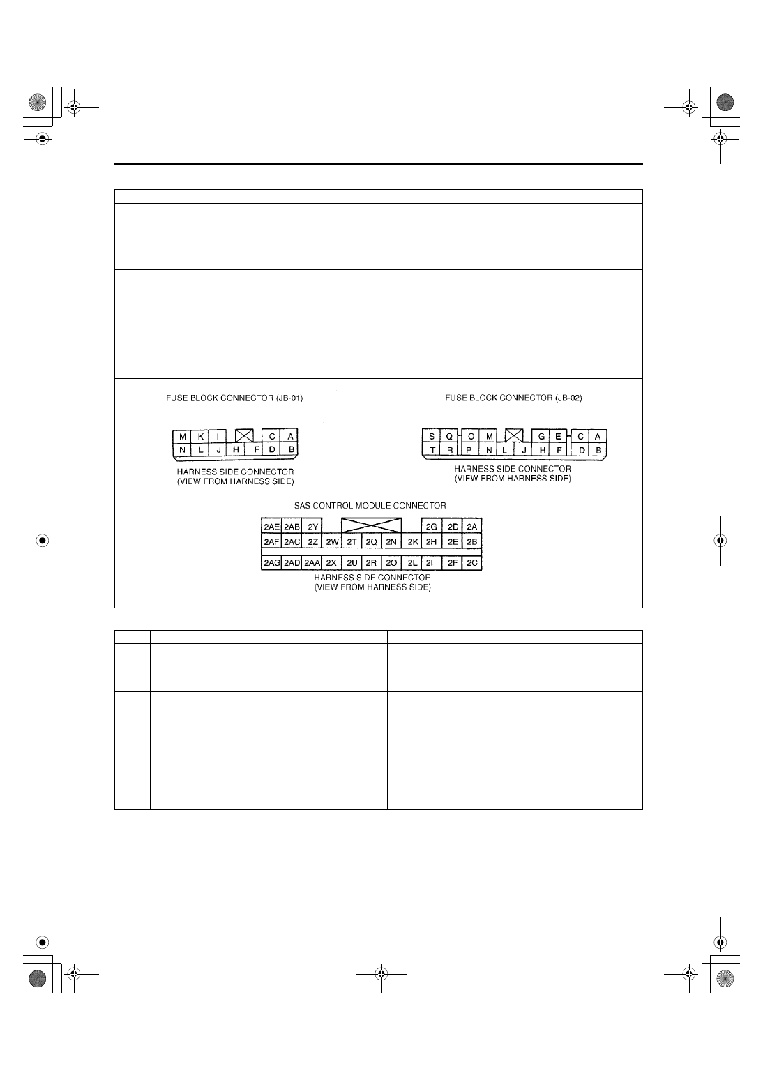
— Wiring harness between fuse block connector (JB–01) terminal B and SAS control module 

connector terminal 2E.

— Wiring harness between fuse block connector (JB–02) terminal D and SAS control module 

connector terminal 2H.

Weak battery.

Malfunction in wiring harness between battery and SAS control module.

SAS control module malfunction.

STEP

INSPECTION

ACTION

1

INSPECT BATTERY

Measure voltage of battery.

Is voltage more than 9 V?

Yes

Go to next step.

No

Battery is weak.
Inspect charge/discharge system.
(See 01–17–1 BATTERY INSPECTION)

2

INSPECT WIRING HARNESS BETWEEN 
BATTERY AND FUSE BLOCK

Remove driver-side front scuff plate.

Remove driver-side front side trim.

Remove fuse block without disconnecting 
connectors.

Turn ignition switch to ON position.

Measure voltage at terminals B (JB–01) and 
D (JB–02) of fuse block connectors.

Is voltage of at least either terminal more 
than 9 V
?

Yes

Go to next step.

No

Repair wiring harnesses. (Battery—fuse block)

1712-1U-01G(08-02).fm  8 ページ  2001年6月29日 金曜日 午後3時22分

ON-BOARD DIAGNOSTIC 

08–02–9

08–02

End Of Sie

DTC 06

A3U080201046W07

3

INSPECT WIRING HARNESS BETWEEN 
FUSE BLOCK AND SAS CONTROL MODULE

Warning

••••

Handling air bag system components 
improperly can accidentally deploy air 
bag modules and pre-tensioner seat 
belts, which may seriously injure you. 
Read AIR BAG SYSTEM SERVICE 
WARNINGS before handling air bag 
system components.
(See 08–10–3 AIR BAG SYSTEM 
SERVICE WARNINGS)

Turn ignition switch to LOCK position.

Disconnect negative battery cable and wait 
for more than 1 minute.

Remove column cover.

Disconnect clock spring connector.

Remove glove compartment.

Disconnect passenger-side air bag module 
connector.

Disconnect driver- and passenger-side side 
air bag module connectors. (Vehicles with 
side air bag)

Remove B-pillar lower trims.

Disconnect driver-and passenger-side pre-
tensioner seat belt connectors.

Remove left side side wall.

Disconnect all SAS control module 
connectors.

Connect negative battery cable.

Turn ignition switch to ON position.

Measure voltage at terminals 2E and 2H of 
SAS control module connector.

Is voltage of at least either terminal more 
than 9 V
?

Yes

Present malfunction diagnosis:

Replace SAS control module.
(See 08–10–12 SAS CONTROL MODULE REMOVAL/
INSTALLATION)

Past malfunction diagnosis:

Complete inspection by DTC.

No

Replace wiring harness. (Fuse block-SAS control module)

STEP

INSPECTION

ACTION

DTC 06

Driver-side air bag module system

DETECTION 

CONDITION

Warning

••••

Detection conditions are for understanding DTC outline before performing inspection. 
Performing inspection with only detection conditions may cause injury due to operating error 
or damage the system. When performing inspection, always follow diagnostic procedure.

Resistance detected between terminals 2D and 2G of SAS control module is other than 1.85—3.46 
ohm
.

Short circuit in wiring harness related SAS control module terminal 2D or 2G.

POSSIBLE 

CAUSE

Driver-side air bag module malfunction.

Clock spring malfunction.

Malfunction of connectors between clock spring and SAS control module.

Open or short circuit in wiring harness between clock spring and SAS control module.

SAS control module malfunction.

1712-1U-01G(08-02).fm  9 ページ  2001年6月29日 金曜日 午後3時22分

ON-BOARD DIAGNOSTIC 

08–02–10

Diagnostic procedure

STEP

INSPECTION

ACTION

1

INSPECT SEPARATOR* OF CLOCK SPRING

Warning

••••

Handling air bag system components 
improperly can accidentally deploy air 
bag modules and pre-tensioner seat 
belts, which may seriously injure you. 
Read AIR BAG SYSTEM SERVICE 
WARNINGS before handling air bag 
system components.
(See 08–10–3 AIR BAG SYSTEM 
SERVICE WARNINGS)

Turn ignition switch to LOCK position.

Disconnect negative battery cable and wait 
for more than 1 minute.

Remove driver-side air bag module.
(See 08–10–5 DRIVER-SIDE AIR BAG 
MODULE REMOVAL/INSTALLATION)

Is separator* of clock spring okay?

Yes

Present malfunction diagnosis:

Go to next step.

Past malfunction diagnosis:

Go to Step 6.

No

Replace clock spring.
(See 08–10–9 CLOCK SPRING REMOVAL/
INSTALLATION)

2

VERIFY WHETHER MALFUNCTION IS IN 
DRIVER-SIDE AIR BAG MODULE OR OTHER 
PARTS

Connect leads of SST (Fuel And 
Thermometer checker) or apply 2 ohms 
resistor to clock spring terminals 3A and 3B.

Set resistance of SST (Fuel And 
Thermometer checker) to 2 ohms.

Connect negative battery cable.

Turn ignition switch to ON position.

Is DTC 06 indicated?

Yes

Go to next step.

No

Replace driver-side air bag module.
(See 08–10–5 DRIVER-SIDE AIR BAG MODULE 
REMOVAL/INSTALLATION)

3

INSPECT SEPARATOR* OF CLOCK SPRING 
CONNECTOR

Turn ignition switch to LOCK position.

Disconnect negative battery cable and wait 
for more than 1 minute.

Remove column cover.

Disconnect clock spring connector.

Is separator* of clock spring connector okay?

Yes

Go to next step.

No

Replace wiring harness.

4

VERIFY WHETHER MALFUNCTION IS IN 
CLOCK SPRING OR OTHER PARTS

Connect leads of SST (Fuel And 
Thermometer checker) or apply 2 ohms 
resistor clock spring connector terminals A 
and B.

Set resistance of SST (Fuel And 
Thermometer checker) to 2 ohms.

Connect negative battery cable.

Turn ignition switch to ON position.

Is DTC 06 indicated?

Yes

Go to next step.

No

Replace clock spring.
(See 08–10–9 CLOCK SPRING REMOVAL/
INSTALLATION)

1712-1U-01G(08-02).fm  10 ページ  2001年6月29日 金曜日 午後3時22分

ON-BOARD DIAGNOSTIC 

08–02–11

08–02

*

: Consists of 2 parts of female connector that separate the short bar from the terminal when connected to the 

male connector.

End Of Sie

5

INSPECT WIRING HARNESS BETWEEN 
CLOCK SPRING AND SAS CONTROL 
MODULE

Turn ignition switch to LOCK position.

Disconnect negative battery cable and wait 
for more than 1 minute.

Remove glove compartment.

Disconnect passenger-side air bag module 
connector.

Disconnect driver- and passenger-side side 
air bag module connectors. (Vehicles with 
side air bag)

Remove B-pillar lower trims.

Disconnect driver-and passenger-side pre-
tensioner seat belt connectors.

Remove left side side wall.

Disconnect all SAS control module 
connectors.

Are wiring harnesses okay?

Yes

Replace SAS control module.
(See 08–10–12 SAS CONTROL MODULE REMOVAL/
INSTALLATION)

No

Replace wiring harnesses.

6

INSPECT SEPARATOR* OF CLOCK SPRING 
CONNECTOR

Remove column cover.

Disconnect clock spring connector.

Is separator* of clock spring connector okay?

Yes

Go to next step.

No

Replace wiring harness.

7

INSPECT CLOCK SPRING

Remove clock spring.
(See 08–10–9 CLOCK SPRING REMOVAL/
INSTALLATION)

Inspect clock spring.
(See 08–10–10 CLOCK SPRING 
INSPECTION)

Is clock spring okay?

Yes

Go to next step.

No

Replace wiring harness.

8

INSPECT WIRING HARNESS BETWEEN 
CLOCK SPRING AND SAS CONTROL 
MODULE

Remove glove compartment.

Disconnect passenger-side air bag module 
connector.

Disconnect driver- and passenger-side side 
air bag module connectors. (Vehicles with 
side air bag)

Remove B-pillar lower trims.

Disconnect driver-and passenger-side pre-
tensioner seat belt connectors.

Remove left side side wall.

Disconnect all SAS control module 
connectors.

Inspect wiring harness between terminal 2D 
of SAS control module connector and 
terminal A of clock spring connector, and 
between terminal 2G of SAS control module 
connector and terminal B of clock spring 
connector for following.
— Short to ground
— Short to power supply
— Open circuit

Are wiring harnesses okay?

Yes

Replace driver-side air bag module.
(See 08–10–5 DRIVER-SIDE AIR BAG MODULE 
REMOVAL/INSTALLATION)

No

Replace wiring harness.

STEP

INSPECTION

ACTION

1712-1U-01G(08-02).fm  11 ページ  2001年6月29日 金曜日 午後3時22分


Content   ..  283  284  285  286   ..