Mazda Protege 5. Manual - part 282
 

  Index      Mazda     Mazda Protege 5 - service repair manual 2002 year


Search            


Content   ..  280  281  282  283   ..


Mazda Protege 5. Manual - part 282


CONTROL SYSTEM 

07–40–12

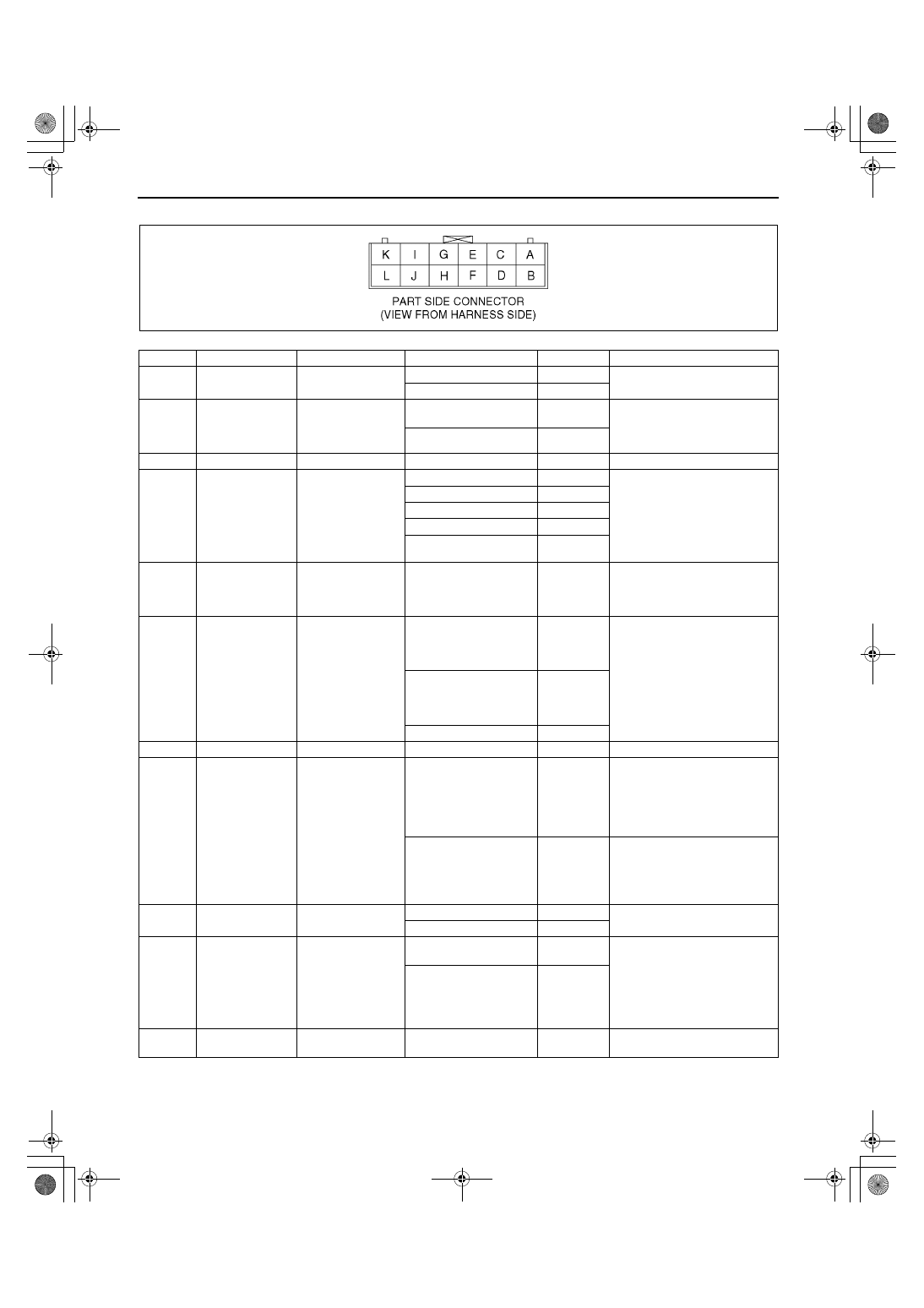
Terminal voltage list (Reference)

Terminal

Signal

Connected to 

Test condition

Voltage (V)

Action

A

Fresh signal

Air intake actuator

RECIRCULATE

0.3

•

Inspect air intake actuator

•

Inspect related harness

FRESH

11.3

B

A/C signal

A/C amplifier

Fan switch ON, A/C 
switch ON

1.45

•

Inspect for continuity or 
short circuit (Climate control 
unit—A/C amplifier: B—C)

•

Inspect A/C amplifier

Fan switch OFF

10.3

C

—

—

—

—

—

D

A/C signal

Fan switch

Fan switch OFF

B+

•

Inspect for continuity or 
short circuit (Climate control 
unit—Fan switch, Resistor: 
D—C, C)

•

Inspect fan switch

•

Inspect resistor

•

Inspect related harness

Fan switch 1st

0.12

Fan switch 2nd

0.65

Fan switch 3rd

0.60

Fan switch 4th

0.30

E

GND

Ground

Under any condition

Below 1.0

•

Inspect for continuity (A/C 
amplifier—Ground: E—
GND)

•

Inspect related harness

F

TNS signal

Panel light control 
switch

Light switch ON and 
panel light control switch 
at max.
illumination

0.2

•

Inspect for continuity or 
short circuit (Climate control 
unit—Panel light control 
switch: F—C)

•

Inspect panel light control 
switch

•

Inspect related harness

Light switch ON and 
panel light control switch 
at min.
illumination

9.7

Light switch OFF

0.1

G

—

—

—

—

—

H

TNS signal

TNS relay

Light switch ON

B+

•

Inspect for continuity or 
short circuit (Climate control 
unit—TNS relay: H—C)

•

Inspect TNS relay

•

Inspect headlight switch

•

Inspect related harness

Light switch OFF

Below 1.0

•

Inspect for short circuit 
(Climate control unit—TNS 
relay: H—C)

•

Inspect TNS relay

•

Inspect headlight switch

I

Recirculate signal

Air intake actuator

RECIRCULATE

11.3

•

Inspect air intake actuator

•

Inspect related harness

FRESH

0.3

J

Rear window 
defroster relay 
control signal

Rear window 
defroster relay

Rear window defroster 
switch ON

0.1

•

Inspect for continuity or 
short circuit (Climate control 
unit—Rear window defroster 
relay: J—E)

•

Inspect rear window 
defroster relay

•

Inspect related harness

Rear window defroster 
switch OFF

B+

K

Power supply

ROOM 10 A fuse

Under any condition

B+

•

Inspect ROOM 10 A fuse

•

Inspect related harness

Y3E8540W027

1712-1U-01G(07-40).fm  12 ページ  2001年6月29日 金曜日 午前10時21分

CONTROL SYSTEM 

07–40–13

07–40

Fan switch

1. Remove the climate control unit.
2. Inspect for continuity between the fan switch 

terminals using an ohmmeter.

•

If not as specified, replace the fan switch.

End Of Sie

A/C AMPLIFIER INSPECTION

A3U074061790W01

Note

•

A/C amplifier controls A/C signal as shown 
in the figure at right.

1. Remove the glove compartment.
2. Pull out the A/C amplifier with the connector still 

connected.

3. Turn the ignition switch to ON position.
4. Measure the voltage at each A/C amplifier 

terminal or climate control unit terminal and refer 
to the terminal voltage list.

•

If not as specified, inspect the parts listed 
under “Action” and the related wiring harness.

•

If there is no malfunction under “Action”, 
replace the A/C amplifier.

L

IG2

A/C 15 A fuse

Ignition switch at ON 
position

B+

•

Inspect for continuity 
(Climate control unit—Fuse : 
L—A/C 15 A fuse)

•

Inspect A/C 15 A fuse

•

Inspect related harness

Ignition switch at LOCK 
position

0.1

•

Inspect for short circuit 
(Climate control unit—Fuse: 
L—A/C 15 A fuse)

Terminal

Signal

Connected to 

Test condition

Voltage (V)

Action

Y3E8540W025

Y3E8540W026

Z3U0740W019

1712-1U-01G(07-40).fm  13 ページ  2001年6月29日 金曜日 午前10時21分

CONTROL SYSTEM 

07–40–14

Terminal Voltage List (Reference)

End Of Sie

Terminal

Signal

Connected to 

Test condition

Voltage (V)

Action

A

IG2

A/C 15 A fuse

Ignition switch at ON 
position

B+

•

Inspect for continuity or 
short circuit (Fuse —A/C 
amplifier:A/C 15 A fuse —A)

•

Inspect A/C 15 A fuse

•

Inspect related harness

Ignition switch at LOCK 
position

Below 1.0

B

A/C signal

Refrigerant 
pressure switch

Fan switch at 1st 
position, A/C switch ON

0.6

•

Inspect for continuity or 
short circuit (PCM—
Refrigerant pressure 
switch:4F—B) (Refrigerant 
pressure switch—A/C 
amplifier:A—B)

•

Inspect terminal voltage of 
A/C amplifier (C)

•

Inspect refrigerant pressure 
switch

•

Inspect PCM
(See 01–40B–7 PCM 
INSPECTION [FS] )
(See 01–40A–7 PCM 
INSPECTION [ZM] )

•

Inspect related harness

Fan switch OFF

12

C

A/C switch

A/C switch

Fan switch OFF

11.5

•

Inspect for short circuit (A/C 
amplifier—climate control 
unit: C—B) 

•

Inspect terminal voltage of 
A/C amplifier (A)

Fan switch at 1st 
position, A/C switch ON

0.6

•

Inspect for continuity or 
short circuit (A/C amplifier—
climate control unit: C—B) 
(climate control unit—fan 
switch:A—C)

•

Inspect A/C switch

•

Inspect fan switch

D

—

—

—

—

—

E

—

—

—

—

—

F

—

—

—

—

—

Y3E8540W024

1712-1U-01G(07-40).fm  14 ページ  2001年6月29日 金曜日 午前10時21分

TECHNICAL DATA 

07–50–1

07–50

07–50

TECHNICAL DATA

HVAC TECHNICAL DATA  . . . . . . . . . . .  07–50–1

End of Toc

HVAC TECHNICAL DATA

A3U075001038W01

End Of Sie

Item

Specification

REFRIGERANT SYSTEM

Refrigerant

Type

R-134a

Regular amount
(approximate quantity)

(g {oz})

600 {21.2}

BASIC SYSTEM

A/C compressor

Lubricating oil

Type

ATMOS GU10

Sealed volume 
(approximate quantity)

150 {150, 5.07}

(ml {cc, fl oz}/rev)

CONTROL SYSTEM

Magnetic clutch

Clearance 

(mm {in})

0.4—0.6 {0.016—0.023}

1712-1U-01G(07-50).fm  1 ページ  2001年6月29日 金曜日 午前10時21分


Content   ..  280  281  282  283   ..