Mazda Protege 5. Manual - part 183


  Index      Mazda     Mazda Protege 5 - service repair manual 2002 year


Search            


Content   ..  181  182  183  184   ..


Mazda Protege 5. Manual - part 183


CONTROL SYSTEM [FS]

01–40B–41

01–40B

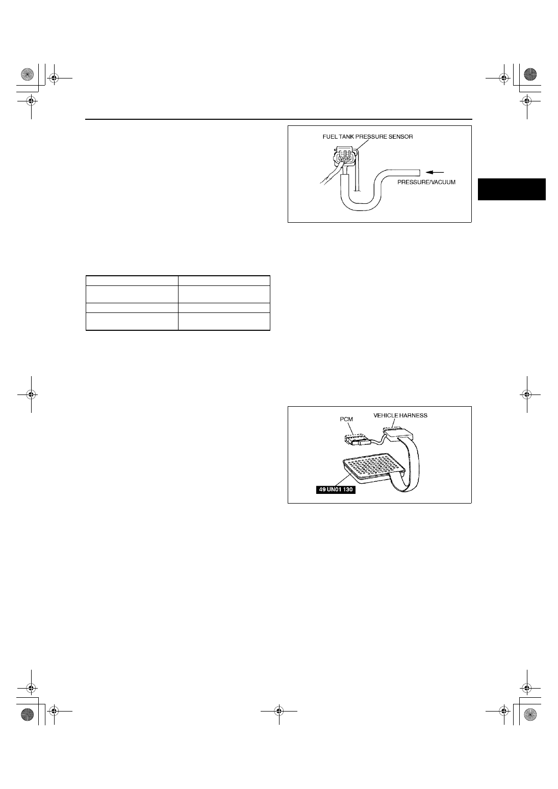
5. Apply pressure then vacuum to the fuel tank 

pressure sensor according to the following 
procedure.

Note

The output voltage varies with the 
measuring condition.

6. Decrease the applied pressure from +6.66 kPa 

{+50 mmHg, +1.97 inHg} to –6.66 kPa {–50 
mmHg, –1.97 inHg}
 and verify that the PCM 
terminal 62 voltage decreases accordingly as 
specified.

If not as specified, replace the fuel tank 
pressure sensor.

If fuel tank pressure sensor is okay, but PCM terminal 62 voltage is out of specification, carry out the 
“Circuit Open/Short Inspection”.

Specification

*

: Measuring condition is as follows

Input voltage: 5.0 V
Barometric pressure: 101.3 kPa {760 mmHg, 29.9 inHg} (Absolute pressure)
Barometric temperature: 30—100 

°°°°

C {0—182 

°°°°

F}

Circuit Open/Short Inspection

1. Remove the PCM. (See 01–40B–7 PCM REMOVAL/INSTALLATION [FS].)
2. Connect the SST (104 Pin Breakout Box) to the 

PCM as shown.

3. Tighten the connector attaching screw.

Tightening torque

7.9—10.7 N·m 

{80—110 kgf·cm, 69.5—95.4 in·lbf}

4. Inspect for an open or short circuit in the following 

wiring harnesses by probing the applicable 
sensor and SST (104 Pin Breakout Box) terminals 
with ohmmeter leads.

If there is an open or short circuit, repair or 
replace wiring harnesses.

If there is no open or short circuit, replace the fuel tank pressure sensor.

Open circuit

Fuel tank pressure signal circuit (Fuel tank pressure sensor connector terminal B and PCM connector 
terminal 62)

Constant voltage circuit (Fuel tank pressure sensor connector terminal C and PCM connector terminal 90)

GND circuit (Fuel tank pressure sensor connector terminal A and PCM connector terminal 91)

Applied pressure

Output voltage (V)*

–6.66 kPa 

{–50 mmHg, –1.97 inHg}

0.45—0.55

0 kPa {0 mmHg, 0 inHg}

2.25—2.75

+6.66 kPa 

{+50 mmHg, +1.97 inHg}

4.05—4.95

X3U140WB4

X3U140WB3

1712-1U-01G(01-40B).fm  41 ページ  2001年6月29日 金曜日 午前9時51分

CONTROL SYSTEM [FS]

01–40B–42

Short circuit

Fuel tank pressure signal circuit (Fuel tank 
pressure sensor connector terminal B and 
PCM connector terminal 62)

Constant voltage circuit (Fuel tank pressure 
sensor connector terminal C and PCM 
connector terminal 90)

5. Reconnect the fuel tank pressure sensor 

connector.

End Of Sie

CLUTCH SWITCH INSPECTION [FS]

A3U014018660W01

Note

Perform the following test only when directed.

1. Verify that the clutch switch is installed properly.
2. Disconnect the negative battery cable.
3. Remove the clutch switch. (See 05–10–5 

CLUTCH PEDAL REMOVAL/INSTALLATION.)

4. Inspect the continuity between the clutch switch 

terminals using an ohmmeter.

If not as specified, replace the clutch switch.

If the clutch switch is okay, but PID value or 
PCM terminal 6 voltage is out of specification, 
carry out the “Circuit Open/Short Inspection”.

Circuit Open/Short Inspection

1. Remove the PCM. (See 01–40B–7 PCM REMOVAL/INSTALLATION [FS].)
2. Connect the SST (104 Pin Breakout Box) to the 

PCM as shown.

3. Tighten the connector attaching screw.

Tightening torque

7.9—10.7 N·m 

{80—110 kgf·cm, 69.5—95.4 in·lbf}

4. Inspect for an open or short circuit in the following 

wiring harnesses by probing the applicable 
sensor and SST (104 Pin Breakout Box) terminals 
with ohmmeter leads.

If there is an open or short circuit, repair or 
replace wiring harnesses.

If there is no open or short circuit, replace the clutch switch.

X3U140WB5

Z3U0140W029

Z3U0140W030

X3U140WE8

1712-1U-01G(01-40B).fm  42 ページ  2001年6月29日 金曜日 午前9時51分

CONTROL SYSTEM [FS]

01–40B–43

01–40B

Open circuit

Signal circuit (Clutch switch connector terminal B and PCM connector terminal 6 through common 
connector)

GND circuit (Clutch switch connector terminal A and GND)

Short circuit

Signal circuit (Clutch switch connector 
terminal B and PCM connector terminal 6 
through common connector to GND)

5. Install the clutch switch.

End Of Sie

NEUTRAL SWITCH INSPECTION [FS]

A3U014017640W01

Note

Perform the following test only when directed.

1. Disconnect the negative battery cable.
2. Remove the neutral switch.
3. Inspect for continuity between the neutral switch 

terminals using an ohmmeter.

If not as specified, replace the neutral switch.

If the neutral switch is okay, but PID value or 
PCM terminal 64 voltage is out of 
specification, carry out the “Circuit Open/
Short Inspection”.

Circuit Open/Short Inspection

1. Remove the PCM. (See 01–40B–7 PCM REMOVAL/INSTALLATION [FS].)
2. Connect the SST (104 Pin Breakout Box) to the 

PCM as shown.

3. Tighten the connector attaching screw.

Tightening torque

7.9—10.7 N·m 

{80—110 kgf·cm, 69.5—95.4 in·lbf}

4. Inspect for an open or short circuit in the following 

wiring harnesses by probing the applicable 
sensor and SST (104 Pin Breakout Box) terminals 
with ohmmeter leads.

If there is an open or short circuit, repair or 
replace wiring harnesses.

If there is no open or short circuit, replace the neural switch.

Open circuit

Signal circuit (Neutral switch connector terminal A and PCM connector terminal 64 through common 
connector)

GND circuit (Neutral switch connector terminal B and GND through common connector)

Short circuit

Signal circuit (Neutral switch connector terminal A and PCM terminal 64 through common connector to 
GND)

Z3U0140W031

A3U0140W004

X3U140WE3

X3U140WE8

1712-1U-01G(01-40B).fm  43 ページ  2001年6月29日 金曜日 午前9時51分

CONTROL SYSTEM [FS]

01–40B–44

5. Install the neutral switch.

End Of Sie

POWER STEERING PRESSURE (PSP) SWITCH INSPECTION [FS]

A3U014032230W01

Continuity Inspection

Note

Perform the following test only when directed.

1. Inspect as follows if the power steering is inoperative. (See 06–12–3 POWER STEERING FLUID 

INSPECTION.)

Power steering fluid level

Power steering fluid leakage

Power steering fluid pressure

2. Disconnect the PSP switch connector.
3. Start the engine.
4. Inspect for continuity between the PSP switch terminal and GND using an ohmmeter.

If not as specified, replace the PSP switch.

If the PSP switch is okay, but PID value or PCM terminal 31 voltage are out of specification, carry out the 
“Circuit Open/Short Inspection”.

Circuit Open/Short Inspection

1. Remove the PCM. (See 01–40B–7 PCM REMOVAL/INSTALLATION [FS].)
2. Connect the SST (104 Pin Breakout Box) to the 

PCM as shown.

3. Tighten the connector attaching screw.

Tightening torque

7.9—10.7 N·m 

{80—110 kgf·cm, 69.5—95.4 in·lbf}

4. Inspect for an open or short circuit in the following 

wiring harnesses by probing the applicable 
sensor and SST (104 Pin Breakout Box) terminals 
with ohmmeter leads.

If there is an open or short circuit, repair or 
replace wiring harnesses.

If there is no open or short circuit, replace the PSP switch.

Open circuit

PSP signal circuit (PSP switch connector terminal and PCM connector terminal 31 through common 
connector)

GND circuit (PSP switch body and GND)

Short circuit

PSP signal circuit (PSP switch connector terminal and PCM connector terminal 31 through common 
connector to GND)

5. Reconnect the PSP switch connector.

End Of Sie

X3U140WE4

X3U140WE8

1712-1U-01G(01-40B).fm  44 ページ  2001年6月29日 金曜日 午前9時51分


Content   ..  181  182  183  184   ..