Mazda Protege 5. Manual - part 181
CONTROL SYSTEM [FS]
01–40B–33
01–40B
Resistance Inspection
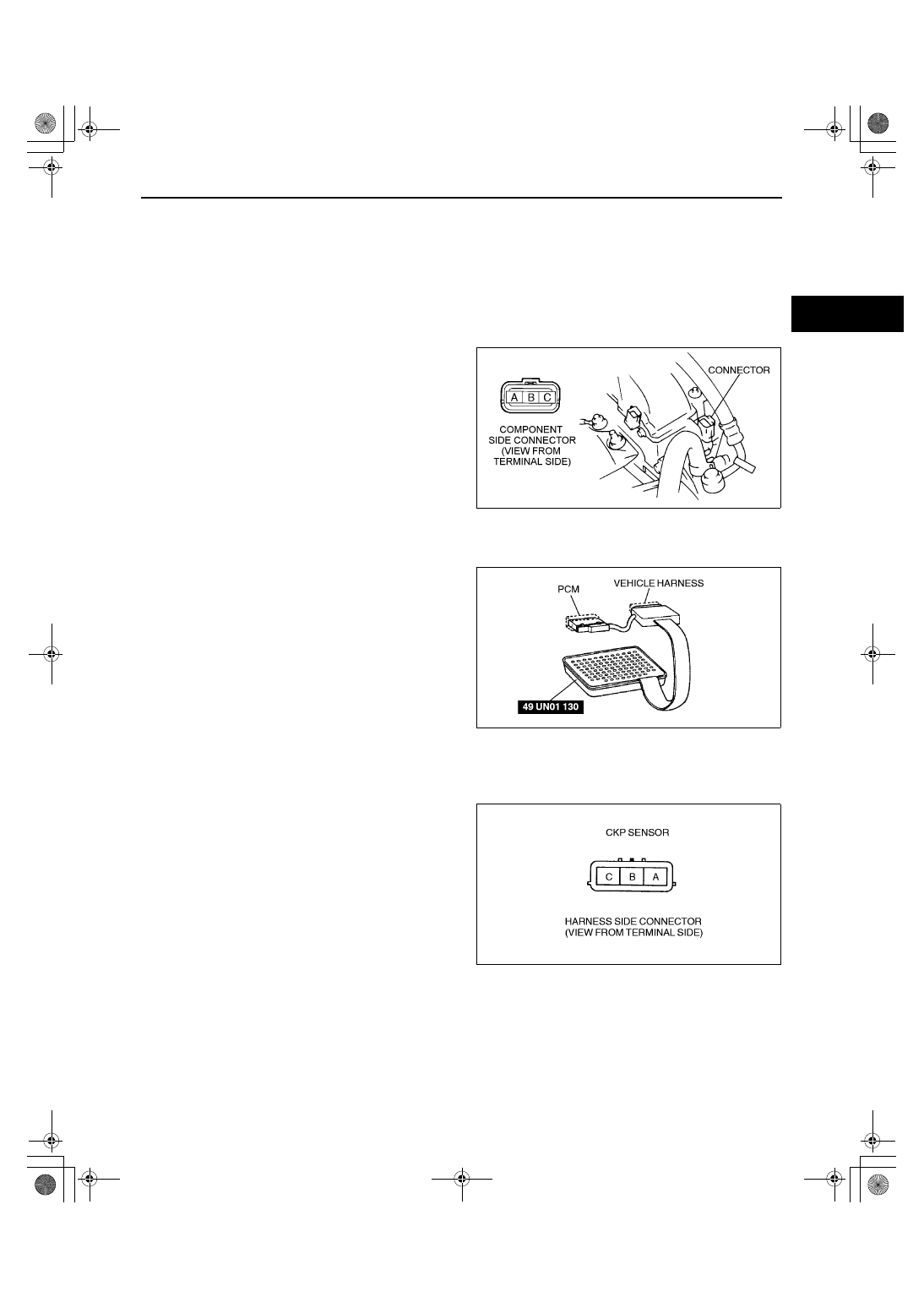
1. Disconnect the CKP sensor connector.
2. Measure the resistance between the CKP sensor terminals A and B using an ohmmeter.
•
If not as specified, replace the CKP sensor.
•
If CKP sensor resistance is okay, but PID value or PCM terminal 21 and 22 voltage is out of specification,
carry out the “Circuit Open/Short Inspection”.
Specification
Approx. 550 ohms
Circuit Open/Short Inspection
1. Remove the PCM. (See 01–40B–7 PCM REMOVAL/INSTALLATION [FS].)
2. Connect the SST (104 Pin Breakout Box) to the
PCM as shown.
3. Tighten the connector attaching screw.
Tightening torque
7.9—10.7 N·m
{80—110 kgf·cm, 69.5—95.4 in·lbf}
4. Inspect for an open or short circuit in the following
wiring harnesses by probing the applicable
sensor and SST (104 Pin Breakout Box) terminals
with ohmmeter leads.
•
If there is an open or short circuit, repair or
replace wiring harnesses.
•
If there is no open or short circuit, replace the CKP sensor.
Open circuit
•
CKP signal circuit (CKP sensor connector terminal A and PCM connector terminal 21)
•
CKP signal circuit (CKP sensor connector
terminal B and PCM connector terminal 22)
Short circuit
•
CKP signal circuit (CKP sensor connector
terminal A and PCM connector terminal 21 to
GND)
•
CKP signal circuit (CKP sensor connector
terminal B and PCM connector terminal 22 to
GND)
5. Reconnect the CKP sensor connector.
End Of Sie
Y3U140WB8
X3U140WE8
Y3U140WBP
1712-1U-01G(01-40B).fm 33 ページ 2001年6月29日 金曜日 午前9時51分