Mazda Protege 5. Manual - part 167
 

  Index      Mazda     Mazda Protege 5 - service repair manual 2002 year


Search            


Content   ..  165  166  167  168   ..


Mazda Protege 5. Manual - part 167


CONTROL SYSTEM [ZM]

01–40A–21

01–40A

*

1

: ATX only

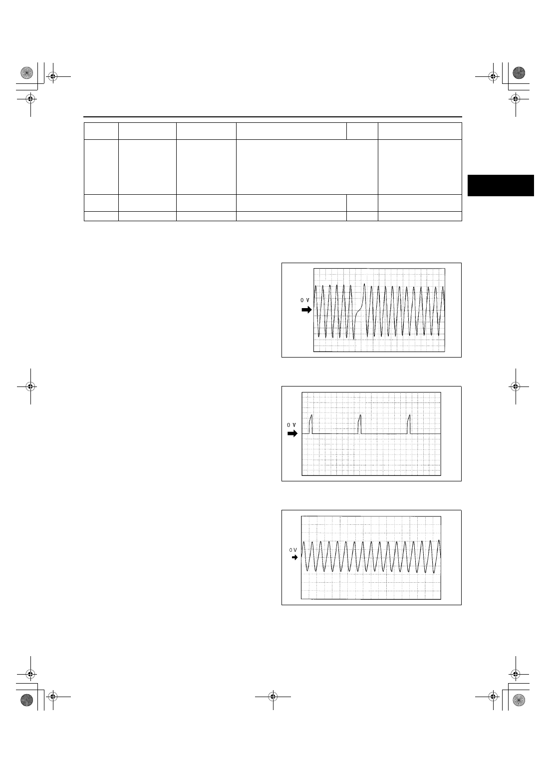
Inspection Using An Oscilloscope (Reference)
Ne signal

•

PCM terminal: 21(+)-22(-)

•

Oscilloscope setting: 2 V/DIV(Y), 2ms/DIV(X), AC 
range

•

Vehicle condition: idle after warm up

IGT signal

•

PCM terminal: 
— IGT1: 26(+)-103(-)
— IGT2: 52(+)-103(-)

•

Oscilloscope setting: 1 V/DIV(Y), 10ms/DIV(X), 
DC range

•

Vehicle condition: idle after warm up

Input/turbine speed signal

•

PCM terminal: 84(+)-23(-)

•

Oscilloscope setting: 0.4 V/DIV(Y), 2.5 ms/
DIV(X), DC range

•

Vehicle condition: idle after warm up

102*

1

Shift solenoid C 
Control

Shift solenoid C

•

Inspect using the wave profile.
(See 01–40A–21 Inspection Using An 
Oscilloscope (Reference))

•

Inspect shift solenoid 
C
(See 05–17–28 
SOLENOID VALVES 
INSPECTION)

•

Inspect related 
harness

103

GND

GND

Under any condition

Below 

1.0

•

Inspect related 
harness

104

—

—

—

—

—

Terminal

Signal

Connected to

Test condition

Voltage 

(V)

Action

Z3U0140W006

Z3U0140W007

Z3U0140W008

1712-1U-01G(01-40A).fm  21 ページ  2001年6月29日 金曜日 午前9時50分

CONTROL SYSTEM [ZM]

01–40A–22

Generator output voltage signal

•

PCM terminal: 30(+)-103(-)

•

Oscilloscope setting: 2 V/DIV(Y), 5 ms/DIV(X), 
DC range

•

Vehicle condition: idle after warm up

Pressure control solenoid control signal
CTP

•

PCM terminal: 80(+)-103(-)

•

Oscilloscope setting: 0.5 V/DIV(Y), 0.1 ms/
DIV(X), DC range

•

Vehicle condition: ignition key at ON (Engine 
OFF) and closed throttle position.

WOT

•

PCM terminal: 81(+)-103(-)

•

Oscilloscope setting: 0.5 V/DIV(Y), 0.1 ms/
DIV(X), DC range

•

Vehicle condition: ignition key at ON (Engine 
OFF) and wide open throttle

Engine speed signal

•

PCM terminal: 48(+)-103(-)

•

Oscilloscope setting: 2 V/DIV(Y), 20 ms/DIV(X), 
DC range

•

Vehicle condition: idle after warm up

Z3U0140W009

Z3U0140W010

Z3U0140W019

Z3U0140W011

1712-1U-01G(01-40A).fm  22 ページ  2001年6月29日 金曜日 午前9時50分

CONTROL SYSTEM [ZM]

01–40A–23

01–40A

Generator field coil control signal

•

PCM terminal: 53(+)-103(-)

•

Oscilloscope setting: 0.2 V/DIV(Y), 2ms/DIV(X), 
DC range

•

Vehicle condition: idle after warm up

Vehicle speed signal

•

PCM terminal: 58(+)-103(-)

•

Oscilloscope setting: 1 V/DIV(Y), 2.5 ms/DIV(X), 
DC range

•

Vehicle condition: drive the vehicle with 32 km/h 
[20 mph]

Purge control signal

•

PCM terminal: 67(+)-103(-)

•

Oscilloscope setting: 4 V/DIV(Y), 20 ms/DIV(X), 
DC range

•

Vehicle condition: idle after warm up

Fuel injection signal

•

PCM terminal
— No.1:75(+)-103(-)
— No.2:101(+)-103(-)
— No.3:74(+)-103(-)
— No.4:100(+)-103(-)

•

Oscilloscope setting: 2 V/DIV(Y), 5 ms/DIV(X), 
DC range

•

Vehicle condition: idle after warm up

Z3U0140W012

Z3U0140W013

Z3U0140W014

Z3U0140W015

1712-1U-01G(01-40A).fm  23 ページ  2001年6月29日 金曜日 午前9時50分

CONTROL SYSTEM [ZM]

01–40A–24

Shift solenoid A control

•

PCM terminal: 82(+)-103(-)

•

Oscilloscope setting: 5 V/DIV(Y), 5 ms/DIV(X), 
DC range

•

Vehicle condition: drive in the 4th gear

IAC signal

•

PCM terminal: 83(+)-103(-)

•

Oscilloscope setting: 2 V/DIV(Y), 0.5 ms/DIV(X), 
DC range

•

Vehicle condition: idle after warm up

SGC signal

•

PCM terminal: 85(+)-103(-)

•

Oscilloscope setting: 2 V/DIV(Y), 20 ms/DIV(X), 
DC range

•

Vehicle condition: idle after warm up

Shift solenoid B control signal

•

PCM terminal: 99(+)-103(-)

•

Oscilloscope setting: 5 V/DIV(Y), 5ms/DIV(X), DC 
range

•

Vehicle condition: Drive in D range, 1st gear

Z3U0140W016

Z3U0140W017

Z3U0140W018

Z3U0140W016

1712-1U-01G(01-40A).fm  24 ページ  2001年6月29日 金曜日 午前9時50分


Content   ..  165  166  167  168   ..