Mazda Protege 5. Manual - part 166
 

  Index      Mazda     Mazda Protege 5 - service repair manual 2002 year


Search            


Content   ..  164  165  166  167   ..


Mazda Protege 5. Manual - part 166


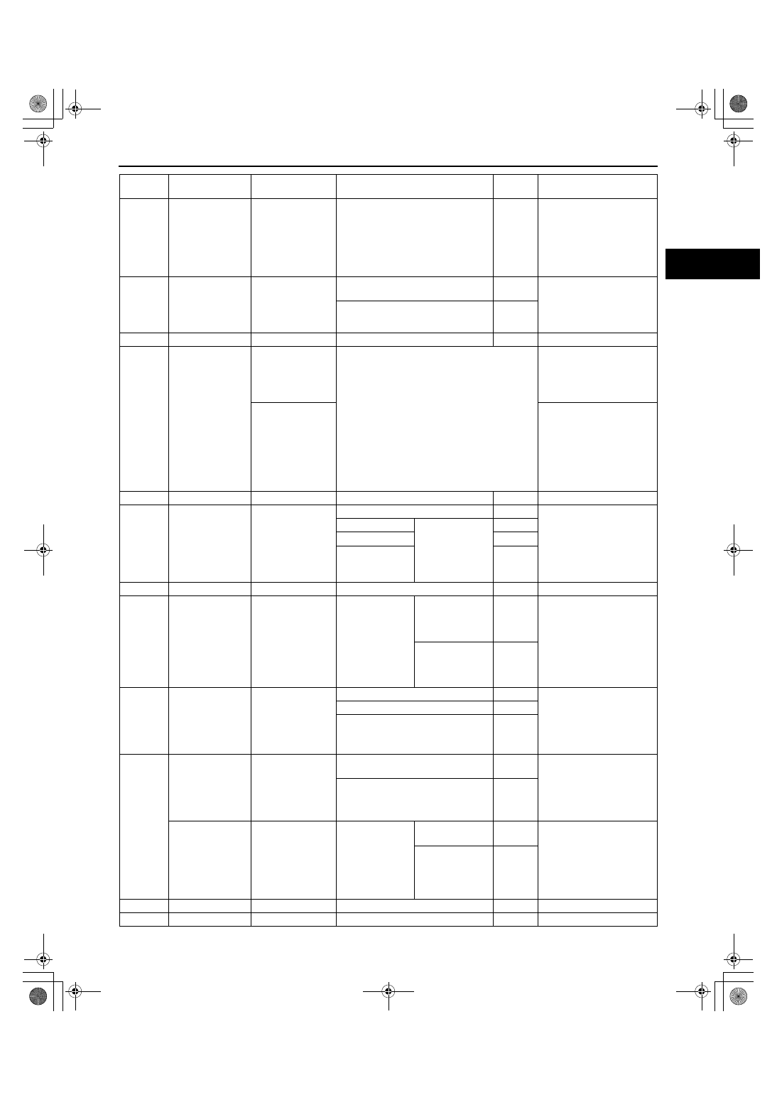
CONTROL SYSTEM [ZM]

01–40A–17

01–40A

55

Back-up power 
supply

Battery (positive 
terminal)

Under any condition

B+

•

Inspect battery
(See 01–17–1 
BATTERY 
INSPECTION)

•

Inspect EGI fuse

•

Inspect related 
harness

56

EGR valve #4 coil 
control

EGR valve 
(terminal F)

Ignition switch ON

Below 

1.0

•

Inspect EGR valve
(See 01–16–15 EGR 
VALVE INSPECTION)

•

Inspect related 
harness

Idle

Below 

1.0

57

—

—

—

—

—

58

Vehicle speed

Speedometer 
(MTX)

•

Inspect using the wave profile.
(See 01–40A–21 Inspection Using An 
Oscilloscope (Reference))

•

Inspect VSS
(See 09–22–4 
Speedometer)

•

Inspect related 
harness

VSS (ATX)

•

Inspect VSS
(See 05–17–27 
VEHICLE 
SPEEDOMETER 
SENSOR (VSS) 
INSPECTION [ATX])

•

Inspect related 
harness

59

—

—

—

—

—

60

HO2S (Front)

HO2S (Front)

Ignition switch ON

0—1.0

•

Inspect HO2S (Front)
(See 01–40A–36 
HO2S (Front and 
Rear) Voltage 
Inspection)

•

Inspect related 
harness

Idle

After warm up

0—1.0

Acceleration

0.5—1.0

Deceleration

0—0.5

61

—

—

—

—

—

62

Fuel tank 
pressure

Fuel tank pressure 
sensor

Ignition switch 
ON

Fuel tank 
pressure 0 kPa 
{0 mmHg, 
0 inHg}

Approx. 

2.5

•

Inspect fuel tank 
pressure sensor
(See 01–40A–40 
FUEL TANK 
PRESSURE SENSOR 
INSPECTION [ZM])

•

Inspect related 
harness

Fuel tank 
pressure 1 kPa 
{7.5 mmHg, 
0.3 inHg}

Approx. 

2.8

63

Fuel tank level

Fuel gauge 
sender unit

Full fuel

0.2—0.5

•

Inspect fuel gauge 
sender unit
(See 09–22–4 Fuel 
Gauge)

•

Inspect related 
harness

Half fuel

2.0—2.8

Empty fuel

3.4—4.4

64

Neutral position 
(MTX)

Neutral switch

Shift lever is at neutral position

Below 

1.0

•

Inspect neutral switch
(See 01–40A–42 
NEUTRAL SWITCH 
INSPECTION [ZM])

•

Inspect related 
harness

Shift lever is not at neutral position

B+

Load/no load 
signal (ATX)

TR switch 
(terminal H)

Ignition switch 
ON

Selector lever is 
at P or N position

Below 

1.0

•

Inspect TR switch
(See 05–17–20 
TRANSAXLE RANGE 
(TR) SWITCH 
INSPECTION)

•

Inspect related 
harness

Others

B+

65

—

—

—

—

—

66

—

—

—

—

—

Terminal

Signal

Connected to

Test condition

Voltage 

(V)

Action

1712-1U-01G(01-40A).fm  17 ページ  2001年6月29日 金曜日 午前9時50分

CONTROL SYSTEM [ZM]

01–40A–18

67

Purge control

Purge solenoid 
valve

•

Inspect using the wave profile.
(See 01–40A–21 Inspection Using An 
Oscilloscope (Reference))

•

Inspect purge solenoid 
valve
(See 01–16–12 
PURGE SOLENOID 
VALVE INSPECTION)

•

Inspect related 
harness

68

EGR valve #1 coil 
control

EGR valve 
(terminal E)

Ignition switch ON

Below 

1.0

•

Inspect EGR valve
(See 01–16–15 EGR 
VALVE INSPECTION)

•

Inspect related 
harness

Idle

Below 

1.0

69

—

—

—

—

—

70

—

—

—

—

—

71

Power supply

Main relay

Ignition switch ON

B+

•

Inspect main relay
(See 09–21–5 RELAY 
INSPECTION)

•

Inspect EGI fuse

•

Inspect related 
harness

Ignition switch off

Below 

1.0

72

EGR valve #2 coil 
control

EGR valve 
(terminal A)

Ignition switch ON

B+

•

Inspect EGR valve
(See 01–16–15 EGR 
VALVE INSPECTION)

•

Inspect related 
harness

Idle

B+

73

—

—

—

—

—

74

Fuel injection (#3) Fuel injector No.3

•

Inspect using the wave profile.
(See 01–40A–21 Inspection Using An 
Oscilloscope (Reference))

•

Inspect fuel injector 
No.3
(See 01–14–24 FUEL 
INJECTOR 
INSPECTION)

•

Inspect related 
harness

75

Fuel injection (#1) Fuel injector No.1

•

Inspect using the wave profile.
(See 01–40A–21 Inspection Using An 
Oscilloscope (Reference))

•

Inspect fuel injector 
No.1
(See 01–14–24 FUEL 
INJECTOR 
INSPECTION)

•

Inspect related 
harness

76

GND

GND

Under any condition

Below 

1.0

•

Inspect related 
harness

77

GND

GND

Under any condition

Below 

1.0

•

Inspect related 
harness

78

—

—

—

—

—

79

K-LINE (serial 
communication)

DLC terminal KLN

Because this terminal is for serial 
communication, good/no good judgment by 
terminal voltage is not possible.

•

Inspect related 
harness

80

Fuel pump control Fuel pump relay

Ignition switch ON

B+

•

Inspect fuel pump 
relay
(See 09–21–5 RELAY 
INSPECTION)

•

Inspect related 
harness

Cranking

Below 

1.0

Idle

Below 

1.0

81*

1

Pressure control 
solenoid (–) 
control

Pressure control 
solenoid

•

Inspect using the wave profile.
(See 01–40A–21 Inspection Using An 
Oscilloscope (Reference))

•

Inspect pressure 
control solenoid
(See 05–17–28 
SOLENOID VALVES 
INSPECTION)

•

Inspect related 
harness

Terminal

Signal

Connected to

Test condition

Voltage 

(V)

Action

1712-1U-01G(01-40A).fm  18 ページ  2001年6月29日 金曜日 午前9時50分

CONTROL SYSTEM [ZM]

01–40A–19

01–40A

82*

1

Shift solenoid A 
control

Shift solenoid A

•

Inspect using the wave profile.
(See 01–40A–21 Inspection Using An 
Oscilloscope (Reference))

•

Inspect shift solenoid A
(See 05–17–28 
SOLENOID VALVES 
INSPECTION)

•

Inspect related 
harness

83

IAC (-)

IAC valve

•

Inspect using the wave profile.
(See 01–40A–21 Inspection Using An 
Oscilloscope (Reference))

•

Inspect IAC valve
(See 01–13A–7 IDLE 
AIR CONTROL (IAC) 
VALVE INSPECTION 
[ZM])

•

Inspect related 
harness

84*

1

Input/turbine 
speed (+)

Input/turbine 
speed sensor

•

Inspect using the wave profile.
(See 01–40A–21 Inspection Using An 
Oscilloscope (Reference))

•

Inspect input/turbine 
speed sensor
(See 05–17–26 
INPUT/TURBINE 
SPEED SENSOR 
INSPECTION)

•

Inspect related 
harness

85

SGC

CMP sensor

•

Inspect using the wave profile.
(See 01–40A–21 Inspection Using An 
Oscilloscope (Reference))

•

Inspect CMP sensor
(See 01–40A–35 
CAMSHAFT 
POSITION (CMP) 
SENSOR 
INSPECTION [ZM])

•

Inspect related 
harness

86

—

—

—

—

—

87

—

—

—

—

—

88

MAF

MAF sensor

Ignition switch ON

0.9—2.0

•

Inspect MAF sensor
(See 01–40A–26 
MASS AIR FLOW 
(MAF)/INTAKE AIR 
TEMPERATURE (IAT) 
SENSOR 
INSPECTION [ZM])

•

Inspect related 
harness

Idle

1.7—2.4

89

Throttle position

TP sensor

Ignition switch 
ON

CTP

0.1—1.1

•

Inspect TP sensor
(See 01–40A–28 
THROTTLE 
POSITION (TP) 
SENSOR 
INSPECTION [ZM])

•

Inspect related 
harness

WOT

3.0—4.6

90

Constant voltage 
(Vref)

TP sensor, EGR 
boost sensor, Fuel 
tank pressure 
sensor

Ignition switch ON

Approx. 

5.0

•

Inspect related 
harness

91

Sensor GND

ECT sensor, IAT 
sensor, EGR 
boost sensor, Fuel 
tank pressure 
sensor, TP 
sensor, HO2S 
(Front, Rear), TFT 
sensor

Under any condition

Below 

1.0

•

Inspect related 
harness

92

Brake

Brake switch

Brake pedal depressed

B+

•

Inspect brake switch
(See 04–11–5 BRAKE 
SWITCH 
INSPECTION)

•

Inspect related 
harness

Brake pedal released

Below 

1.0

Terminal

Signal

Connected to

Test condition

Voltage 

(V)

Action

1712-1U-01G(01-40A).fm  19 ページ  2001年6月29日 金曜日 午前9時50分

CONTROL SYSTEM [ZM]

01–40A–20

93

HO2S (Rear) 
heater control

HO2S (Rear)

Idle

ECT above 70

°

C 

{158 

°

F}

Below 

1.0

•

Inspect HO2S (Rear)
(See 01–40A–37 
HO2S Heater (Front 
and Rear) Resistance 
Inspection)

•

Inspect related 
harness

HO2S (Rear) is 
malfunctioning

B+

94

HO2S (Front) 
heater control

HO2S (Front)

Ignition switch ON (engine stopped)

B+

•

Inspect HO2S (Front) 
heater.
(See 01–40A–37 
HO2S Heater (Front 
and Rear) Resistance 
Inspection)

•

Inspect related 
harness

Approx. 15 seconds after engine 
start with ECT 20—30

°

C {68—86 

°

F}

Below 

1.0

Others

Below 
1.0 

⇔


B+

95

PRC

PRC solenoid 
valve

Ignition switch ON

B+

•

Inspect PRC solenoid 
valve
(See 01–14–31 PRC 
SOLENOID VALVE 
INSPECTION)

•

Inspect related 
harness

After hot start

Below 

1.0

96

A/C control

A/C relay

Idle

A/C switch and 
fan switch on

Below 

1.0

•

Inspect A/C relay
(See 09–21–5 RELAY 
INSPECTION)

•

Inspect related) 
harness

A/C switch off

B+

97

Power supply

Main relay

Ignition switch ON

B+

•

Inspect main relay
(See 09–21–5 RELAY 
INSPECTION)

•

Inspect related 
harness

Ignition switch off

Below 

1.0

98

EGR boost 
sensor switching 
control

EGR boost 
solenoid valve

Ignition switch ON

B+

•

Inspect EGR boost 
solenoid valve
(See 01–16–17 EGR 
BOOST SENSOR 
SOLENOID VALVE 
INSPECTION)

•

Inspect related 
harness

Idle

B+

99*

1

Shift solenoid B 
control

Shift solenoid B

•

Inspect using the wave profile.
(See 01–40A–21 Inspection Using An 
Oscilloscope (Reference))

•

Inspect shift solenoid B
(See 05–17–28 
SOLENOID VALVES 
INSPECTION)

•

Inspect related 
harness

100

Fuel injection (#4) Fuel injector No.4

•

Inspect using the wave profile.
(See 01–40A–21 Inspection Using An 
Oscilloscope (Reference))

•

Inspect fuel injector 
No.4
(See 01–14–24 FUEL 
INJECTOR 
INSPECTION)

•

Inspect related 
harness

101

Fuel injection (#2) Fuel injector No.2

•

Inspect using the wave profile.
(See 01–40A–21 Inspection Using An 
Oscilloscope (Reference))

•

Inspect fuel injector 
No.2
(See 01–14–24 FUEL 
INJECTOR 
INSPECTION)

•

Inspect related 
harness

Terminal

Signal

Connected to

Test condition

Voltage 

(V)

Action

1712-1U-01G(01-40A).fm  20 ページ  2001年6月29日 金曜日 午前9時50分


Content   ..  164  165  166  167   ..