Mazda Protege 5. Manual - part 86
ON-BOARD DIAGNOSTIC [CRUISE CONTROL SYSTEM]
01–02C–9
01–02C
Note
•
When two or more DTCs are indicated, inspect the malfunction with the smallest number first.
End Of Sie
DTC 01
A3U010266350W10
Diagnostic procedure
13
Cruise control switch (Ground circuit)
15
Cruise control module
DTC
Output pattern
Diagnosed circuit
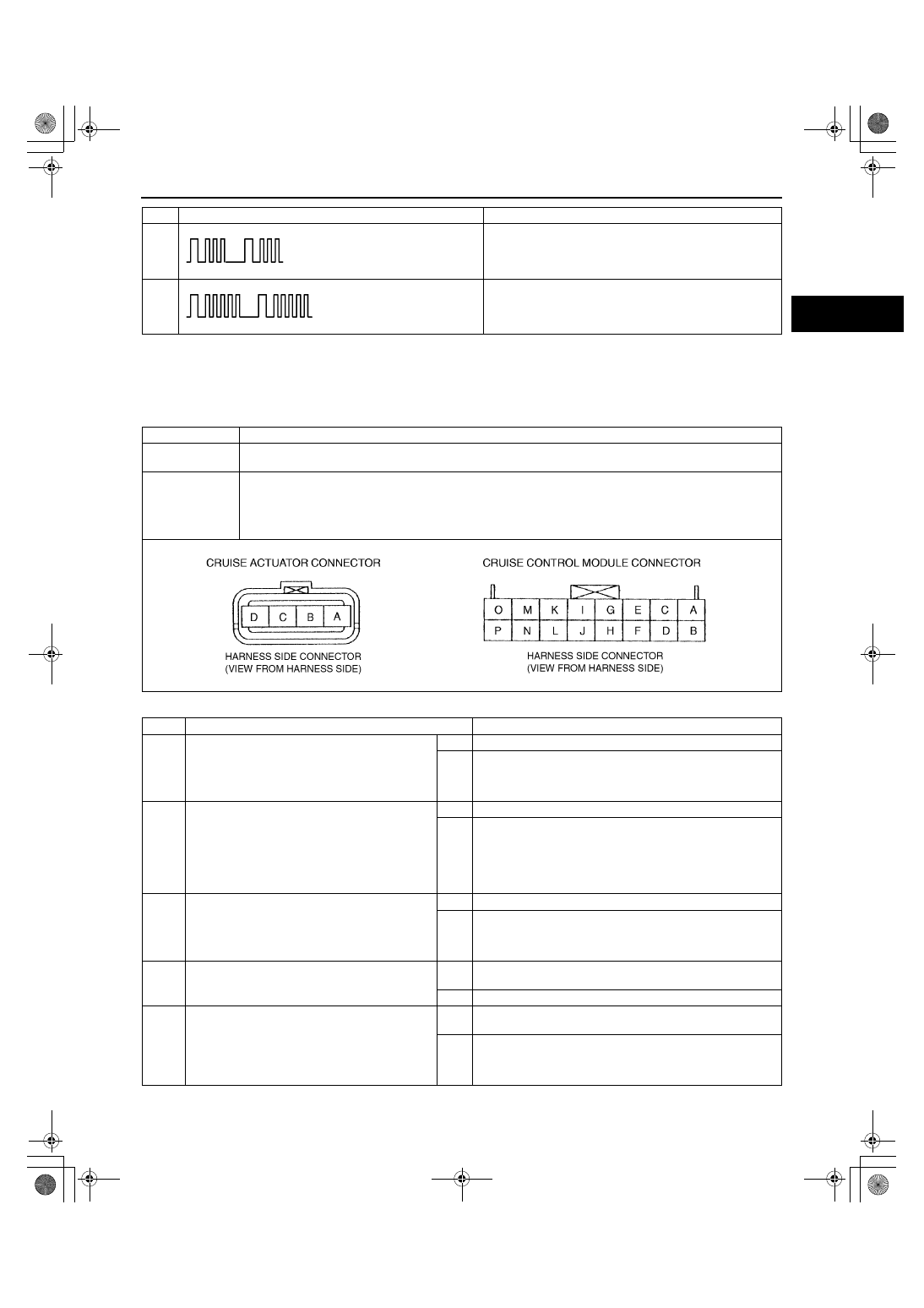
DTC 01
Cruise actuator
DETECTION
CONDITION
•
Voltages detected at terminal A, B or C are not approximately 12 V.
POSSIBLE
CAUSE
•
Cruise control module malfunction
•
Cruise actuator malfunction
•
Open circuit in wiring harness between cruise control module and cruise actuator
•
Open circuit in wiring harness between cruise actuator and brake switch
•
Open circuit in wiring harness between cruise control module and brake switch
STEP
INSPECTION
ACTION
1
INSPECT WIRING HARNESS BETWEEN
CRUISE CONTROL MODULE AND CRUISE
ACTUATOR FOR CONTINUITY
•
Are wiring harnesses between cruise control
module and cruise actuator okay?
Yes
Go to next step.
No
Repair wiring harness.
(Cruise control module—Cruise actuator)
2
INSPECT POWER SUPPLY LINE OF CRUISE
ACTUATOR
•
Disconnect cruise actuator connector.
•
Turn ignition switch to ON position.
•
Turn cruise control main switch on.
•
Is voltage at terminal B of cruise actuator
connector approximately 12 V?
Yes
Go to Step 6.
No
Go to next step.
3
INSPECT WIRING HARNESS BETWEEN
BRAKE SWITCH AND CRUISE ACTUATOR
FOR CONTINUITY
•
Is voltage at terminal 2B of brake switch
connector approximately 12 V?
Yes
Repair wiring harness. (Cruise actuator—Brake switch)
No
Go to next step.
4
INSPECT BRAKE SWITCH
•
Is voltage at terminal 2A of brake switch
connector approximately 12 V?
Yes
Replace brake switch.
(See 04–11–5 BRAKE PEDAL REMOVAL/INSTALLATION)
No
Go to next step.
5
INSPECT CRUISE CONTROL MODULE
•
Remove passenger-side front side trim.
(See 09–17–13 FRONT SIDE TRIM
REMOVAL/INSTALLATION)
•
Is voltage at terminal H of cruise control
module connector approximately 12 V?
Yes
Repair wiring harness.
(Cruise control module—Brake switch)
No
Replace cruise control module.
(See 01–20–2 CRUISE CONTROL MODULE REMOVAL/
INSTALLATION)
1712-1U-01G(01-02C).fm 9 ページ 2001年6月29日 金曜日 午前9時26分