Mazda Protege 5. Manual - part 52
ON-BOARD DIAGNOSTIC [ENGINE CONTROL SYSTEM (FS)]
01–02B–28
End Of Sie
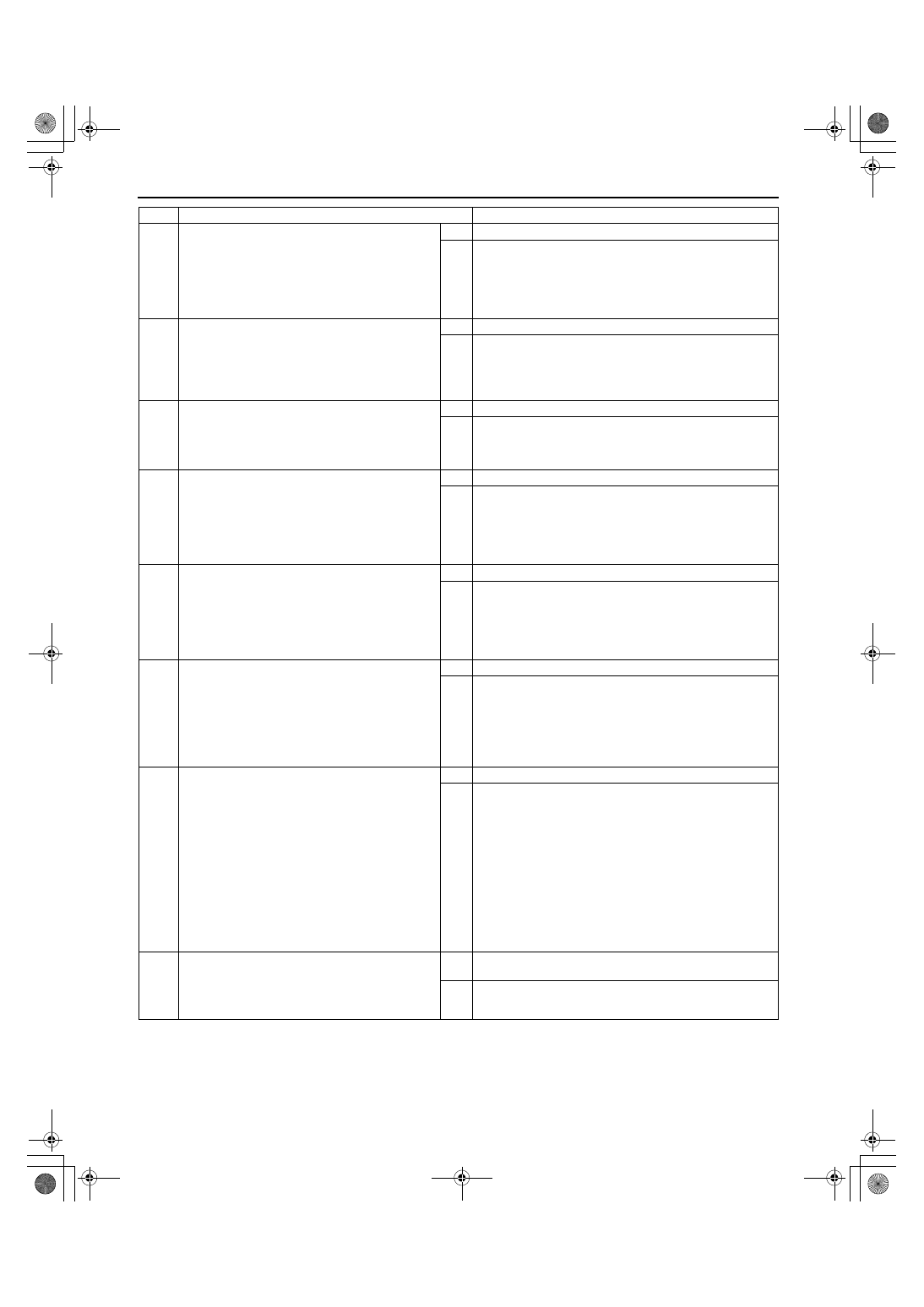
4
INSPECT MAF SENSOR CONNECTOR FOR
POOR CONNECTION
•
Turn ignition key to OFF.
•
Disconnect MAF sensor connector.
•
Check for poor connection (damaged/pulled-
out terminals, corrosion, etc.).
•
Is there malfunction?
Yes Repair or replace terminals, then go to Step 10.
No
Go to next step.
5
CHECK POWER SUPPLY CIRCUIT FOR OPEN
CURCUIT
•
Turn ignition key to ON (Engine OFF).
•
Check voltage at MAF sensor terminal A
(harness-side).
•
Is voltage B+?
Yes Go to next step.
No
Inspect for open circuit in wiring harness between MAF
sensor terminal A (harness-side) and main relay.
Repair or replace harness, then go to Step 10.
6
INSPECT MAF SENSOR GROUND CIRCUIT
FOR OPEN
•
Check for continuity between MAF sensor
terminal B (harness-side) and body ground.
•
Is there continuity?
Yes Go to next step.
No
Check for open circuit between PCM terminal 36 (harness-
side) and MAF sensor terminal B (harness-side).
Repair or replace suspected harness, then go to Step 10.
7
INSPECT PCM CONNECTOR FOR POOR
CONNECTION
•
Turn ignition key to OFF.
•
Disconnect PCM connector.
•
Check for poor connection (damaged/pulled-
out terminals, corrosion, etc.).
•
Is there malfunction?
Yes Repair terminal, then go to Step 10.
No
Go to next step.
8
INSPECT MAF SENSOR SIGNAL CIRCUIT FOR
OPEN CIRCUIT
•
Connect breakout box with PCM disconnected.
•
Check for continuity between MAF sensor
terminal C (harness-side) and breakout box
terminal 88 (harness-side).
•
Is there continuity?
Yes Go to next step.
No
Repair or replace suspected harness, then go to Step 10.
9
INSPECT MAF SENSOR SIGNAL CIRCUIT FOR
SHORTS
•
Check continuity between following circuits:
— MAF sensor terminal C (harness-side) and
body ground
— MAF sensor connector terminal B (harness-
side) and C (harness-side)
•
Is there continuity?
Yes Repair or replace suspected harness, then go to next step.
No
Go to next step.
10
VERIFY TROUBLESHOOTING OF DTC P0102
COMPLETED
•
Make sure to reconnect all disconnected
connectors.
•
Start engine.
•
Clear DTC from memory using WDS or
equivalent.
•
Access MAF PID.
Note
•
MAF PID should indicate above 0 g/s
and 217.8 g/s or below.
•
Is same DTC present?
Yes Replace PCM, then go to next step.
No
Go to next step.
11
VERIFY AFTER REPAIR PROCEDURE
•
Perform “After Repair Procedure”.
(See 01–02B–9 AFTER REPAIR
PROCEDURE [FS].)
•
Is there any DTC present?
Yes Go to applicable DTC inspection.
(See 01–02B–15 DTC TABLE [FS].)
No
Troubleshooting completed.
STEP
INSPECTION
ACTION
1712-1U-01G(01-02B).fm 28 ページ 2001年6月29日 金曜日 午後3時24分