Mazda Protege 5. Manual - part 41
 

  Index      Mazda     Mazda Protege 5 - service repair manual 2002 year


Search            


Content   ..  39  40  41  42   ..


Mazda Protege 5. Manual - part 41


ON-BOARD DIAGNOSTIC [ENGINE CONTROL SYSTEM (ZM)]

01–02A–130

Diagnostic procedure

DTC P1499

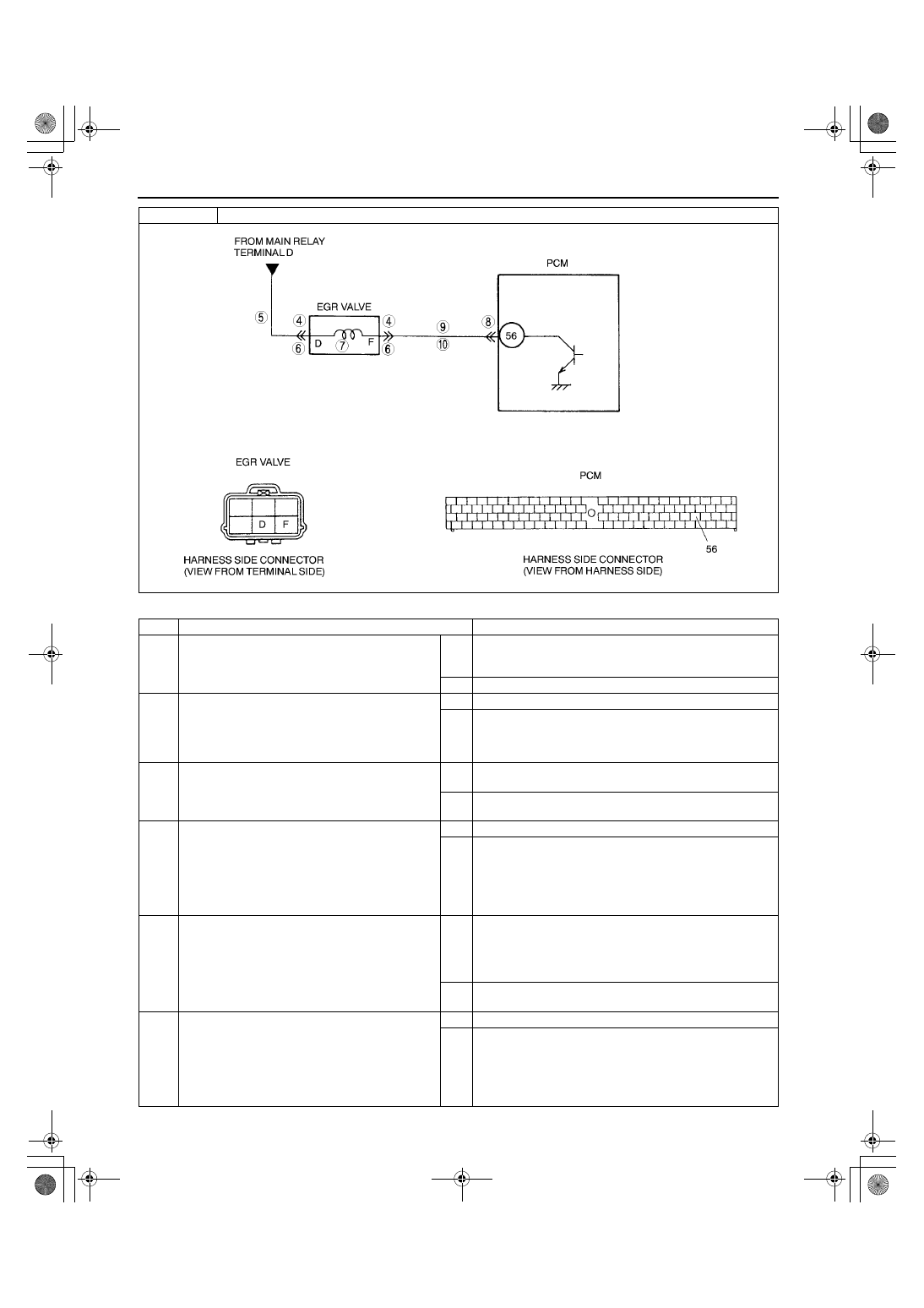
EGR valve stepping motor coil 4 open or short circuit

STEP

INSPECTION

ACTION

1

VERIFY RELATED REPAIR INFORMATION 
AVAILABILITY

•

Check for related Service Bulletins availability.

•

Is any repair information available?

Yes Perform repair or diagnosis according to available repair 

information.

•

If vehicle is not repaired, go to next step.

No

Go to next step.

2

CLASSIFY INTERMITTENT CONCERN OR 
CONTINUOUS CONCERN

•

Turn ignition key to OFF then ON (Engine 
OFF).

•

Is same DTC present?

Yes Go to next step.

No

Refer to intermittent concern.
(See 01–03A–4 INTERMITTENT CONCERN 
TROUBLESHOOTING [ZM].)

3

CLASSIFY POWER CIRCUIT OR CONTROL 
CIRCUIT MALFUNCTION

•

Are same DTC and P1498 present?

Yes Malfunction at EGR valve or power circuit.

Go to next step.

No

Malfunction at EGR valve or control circuit.
Go to Step 6.

4

INSPECT EGR VALVE FOR POOR 
CONNECTION

•

Turn ignition key to OFF.

•

Disconnect EGR valve connector.

•

Check for poor connection (damaged/pulled-
out terminals, corrosion, etc.).

•

Is there malfunction?

Yes Repair or replace terminals, then go to Step 11.

No

Go to next step.

5

INSPECT POWER CIRCUIT FOR OPEN 
CIRCUIT

•

Turn ignition key to ON (Engine OFF).

•

Measure voltage between EGR valve terminal 
D (harness-side) and body ground.

•

Is voltage B+?

Yes Inspect EGR valve coils 3 and 4.

(See 01–16–15 EGR VALVE INSPECTION.)

•

If there is a malfunction, replace EGR valve, and then 
go to Step 11.

•

If there is no malfunction, go to Step 11.

No

Repair or replace harness for open circuit, then go to Step 
11.

6

INSPECT EGR VALVE FOR POOR 
CONNECTION

•

Turn ignition key to OFF.

•

Disconnect EGR valve connector.

•

Check for poor connection (damaged/pulled-
out terminals, corrosion, etc.).

•

Is there malfunction?

Yes Repair or replace terminals, then go to Step 11.

No

Go to next step.

1712-1U-01G(01-02A).fm  130 ページ  2001年6月29日 金曜日 午後2時20分

ON-BOARD DIAGNOSTIC [ENGINE CONTROL SYSTEM (ZM)]

01–02A–131

01–02A

End Of Sie

DTC P1504 [ZM]

A3U010201083W31

7

INSPECT EGR VALVE

•

Measure resistance between EGR valve 
terminal D and F (part-side).

•

Is resistance within 20—24 ohms?

Yes Go to next step.

No

Replace EGR valve, then go to Step 11.

8

INSPECT PCM CONNECTOR FOR POOR 
CONNECTION

•

Disconnect PCM connector.

•

Check for poor connection at terminal 56 
(damaged/pulled-out terminals, corrosion, 
etc.).

•

Is there malfunction?

Yes Repair terminal, then go to Step 11.

No

Go to next step.

9

INSPECT CONTROL CIRCUIT FOR SHORT

•

Check for continuity between EGR valve 
terminal F (harness-side) and body ground.

•

Is there continuity?

Yes Repair or replace harness for short to ground, then go to 

Step 11.

No

Measure voltage between EGR valve terminal F and body 
ground.

•

If voltage is B+, repair or replace harness for short to 
power, then go to next step.

•

If voltage is approx. 0 V, go to next step.

10

INSPECT CONTROL CIRCUIT FOR OPEN 
CIRCUIT

•

Connect breakout box with PCM disconnected.

•

Check for continuity between EGR valve 
terminal F (harness-side) and breakout box 
terminal 56.

•

Is there continuity?

Yes Go to next step.

No

Repair or replace harness for open, then go to next step.

11

VERIFY TROUBLESHOOTING OF DTC P1499 
COMPLETED

•

Make sure to reconnect all disconnected 
connectors.

•

Turn ignition key to OFF, then ON (Engine 
OFF).

•

Is same DTC present?

Yes Replace PCM, then go to next step.

No

Go to next step.

12

VERIFY AFTER REPAIR PROCEDURE

•

Perform “After Repair Procedure”.
(See 01–02A–10 AFTER REPAIR 
PROCEDURE [ZM].)

•

Is there any DTC present?

Yes Go to applicable DTC inspection.

(See 01–02A–15 DTC TABLE [ZM].)

No

Troubleshooting completed.

STEP

INSPECTION

ACTION

DTC P1504

IAC valve circuit malfunction

DETECTION 

CONDITION

•

PCM monitors IAC valve circuit current while IAC duty is within 18—70%. If PCM detects IAC valve circuit 
current below 100 mA (25 

°°°°

C {77 

°°°°

F}) or above 4.5 A (25 

°°°°

C {77 

°°°°

F}) for 1 second, PCM determines that 

IAC valve circuit has malfunction.

Diagnostic support note

•

This is a continuous monitor (CCM).

•

MIL illuminates if PCM detects the above malfunction condition during first drive cycle. Therefore, 
PENDING CODE is not available.

•

FREEZE FRAME DATA is available.

•

DTC is stored in PCM memory.

POSSIBLE 

CAUSE

•

IAC valve circuit malfunction

•

Short to ground between IAC valve terminal A and PCM terminal 54

•

Open circuit between IAC valve terminal A and PCM terminal 54

•

Short to ground between IAC valve terminal B and PCM terminal 83

•

Short to power between IAC valve terminal B and PCM terminal 83

•

Open circuit between IAC valve terminal B and PCM terminal 83

•

Poor connection of IAC valve connector or PCM connector

•

PCM malfunction

1712-1U-01G(01-02A).fm  131 ページ  2001年6月29日 金曜日 午後2時20分

ON-BOARD DIAGNOSTIC [ENGINE CONTROL SYSTEM (ZM)]

01–02A–132

Diagnostic procedure

DTC P1504

IAC valve circuit malfunction

STEP

INSPECTION

ACTION

1

VERIFY FREEZE FRAME DATA HAS BEEN 
RECORDED

•

Has FREEZE FRAME DATA been recorded?

Yes Go to next step.

No

Record FREEZE FRAME DATA on repair order, then go to 
next step.

2

VERIFY RELATED REPAIR INFORMATION 
AVAILABILITY

•

Check for related Service Bulletins availability.

•

Is any repair information available?

Yes Perform repair or diagnosis according to available repair 

information.

•

If vehicle is not repaired, go to next step.

No

Go to next step.

3

CLASSIFY INTERMITTENT CONCERN OR 
CONTINUOUS CONCERN

•

Clear DTC from PCM memory using WDS or 
equipment.

•

Start engine and warm it up completely.

•

Is same DTC detected?

Yes Go to next step.

No

Go to intermittent concern.
(See 01–03A–4 INTERMITTENT CONCERN 
TROUBLESHOOTING [ZM].)

4

INSPECT IAC VALVE CONNECTOR FOR POOR 
CONNECTION

•

Turn ignition key to OFF.

•

Disconnect IAC valve connector.

•

Check for poor connection (damaged/pulled-
out terminals, corrosion, etc.).

•

Is there malfunction?

Yes Repair or replace terminal, then go to Step 14.

No

Go to next step.

5

INSPECT IAC VALVE ELECTRICAL 
MALFUNCTION

•

Measure resistance between IAC valve 
terminals A and B (part-side).

•

Is resistance within 8.7—10.5 ohms?

Yes Go to next step.

No

Replace IAC valve, then go to Step 14.

6

CLASSIFY MALFUNCTION AT POWER 
SUPPLY CIRCUIT OR CONTROL CIRCUIT

•

Turn ignition key to ON (Engine OFF).

•

Measure voltage between IAC valve terminal A 
(harness-side) and body ground.

•

Is voltage B+?

Yes Malfunction at control circuit.

Go to Step 10.

No

Malfunction at power supply circuit.
Go to next step.

1712-1U-01G(01-02A).fm  132 ページ  2001年6月29日 金曜日 午後2時20分

ON-BOARD DIAGNOSTIC [ENGINE CONTROL SYSTEM (ZM)]

01–02A–133

01–02A

End Of Sie

7

INSPECT PCM CONNECTOR FOR POOR 
CONNECTION

•

Turn ignition key to OFF.

•

Disconnect PCM connector.

•

Check for poor connection at terminal 54 
(damaged/pulled-out terminals, corrosion, 
etc.).

•

Is there malfunction?

Yes Repair terminal, then go to Step 14.

No

Go to next step.

8

INSPECT POWER CIRCUIT FOR SHORT TO 
GROUND

•

Turn ignition key to OFF.

•

Check for continuity between IAC valve 
terminal A (harness-side) and body ground.

•

Is there continuity?

Yes Repair or replace harness for short to ground, then go to 

Step 14.

No

Go to next step.

9

INSPECT POWER CIRCUIT FOR OPEN 
CIRCUIT

•

Turn ignition key to OFF

•

Connect breakout box with PCM disconnected.

•

Check for continuity between IAC valve 
terminal A (harness-side) and breakout box 
terminal 54.

•

Is there continuity?

Yes Repair or replace harness for open circuit, then go to Step 

14.

No

Go to Step 14.

10

INSPECT PCM CONNECTOR FOR POOR 
CONNECTION

•

Turn ignition key to OFF.

•

Disconnect PCM connector.

•

Check for poor connection at terminal 83 
(damaged/pulled-out terminals, corrosion, 
etc.).

•

Is there malfunction?

Yes Repair terminal, then go to Step 14.

No

Go to next step.

11

INSPECT CONTROL CIRCUIT FOR SHORT TO 
POWER

•

Turn ignition key to ON (Engine OFF).

•

Measure voltage between IAC valve terminal B 
(harness-side) and body ground.

•

Is voltage B+?

Yes Repair or replace harness for short to power, then go to 

Step 14.

No

Go to next step.

12

INSPECT CONTROL CIRCUIT FOR SHORT TO 
GROUND

•

Turn ignition key to OFF.

•

Check for continuity between IAC valve 
terminal B (harness-side) and body ground.

•

Is there continuity?

Yes Repair or replace harness for short to ground, then go to 

Step 14.

No

Go to next step.

13

INSPECT CONTROL CIRCUIT MALFUNCTION 
FOR OPEN CIRCUIT

•

Connect breakout box with PCM disconnected.

•

Check for continuity between IAC valve 
terminal B (harness-side) and breakout box 
terminal 83.

•

Is there continuity?

Yes Repair or replace harness for open, then go to next step.

No

Go to next step.

14

VERIFY TROUBLESHOOTING OF DTC P1504 
COMPLETED

•

Make sure to reconnect all disconnected 
connectors.

•

Clear DTC from PCM memory using WDS or 
equipment.

•

Start engine and warm it up completely.

•

Is same DTC present?

Yes Replace PCM, then go to next step.

No

Go to next step.

15

VERIFY AFTER REPAIR PROCEDURE

•

Perform “After Repair Procedure”.
(See 01–02A–10 AFTER REPAIR 
PROCEDURE [ZM].)

•

Is there any DTC present?

Yes Go to applicable DTC inspection.

(See 01–02A–15 DTC TABLE [ZM].)

No

Troubleshooting completed.

STEP

INSPECTION

ACTION

1712-1U-01G(01-02A).fm  133 ページ  2001年6月29日 金曜日 午後2時20分


Content   ..  39  40  41  42   ..