Mazda Protege 5. Manual - part 32
ON-BOARD DIAGNOSTIC [ENGINE CONTROL SYSTEM (ZM)]
01–02A–94
End Of Sie
DTC P0500 [ZM]
A3U010201087W06
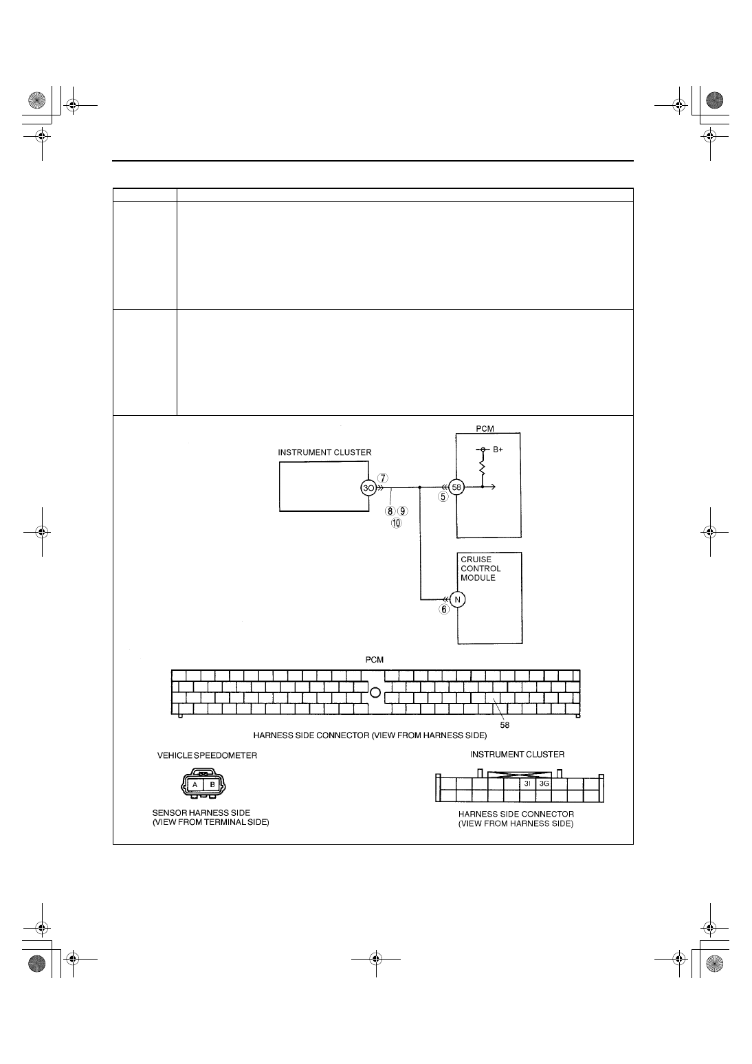
DTC P0500
Vehicle speed sensor (VSS) circuit malfunction (MTX)
DETECTION
CONDITION
•
Vehicle speed signal does not input after following conditions are met:
— Gear is in position other than neutral.
— Load is above 40%.
— Engine speed is 2,000 rpm or above.
Diagnostic support note:
•
This is a continuous monitor (CCM).
•
MIL illuminates if PCM detects the above malfunction conditions in two consecutive drive cycles.
•
PENDING CODE is available if PCM detects the above malfunction condition during first drive cycle.
•
FREEZE FRAME DATA is available.
•
DTC is stored in PCM memory.
POSSIBLE
CAUSE
•
PCM malfunction
•
Instrument cluster malfunction
•
ABS HU/CM malfunction
•
Open circuit between PCM terminal 58 and instrument cluster terminal 3O
•
Short to ground between PCM terminal 58 and instrument cluster terminal 3O
•
Vehicle speedometer sensor malfunction
•
Open circuit between vehicle speedometer sensor terminal A and instrument cluster terminal 3G
•
Short to ground between vehicle speedometer sensor terminal A and instrument cluster terminal 3G
•
Open circuit between vehicle speedometer sensor terminal B and instrument cluster terminal 3I
•
Short to ground between vehicle speedometer sensor terminal B and instrument cluster terminal 3I
1712-1U-01G(01-02A).fm 94 ページ 2001年6月29日 金曜日 午後2時20分