Mazda Protege 5. Manual - part 20
ON-BOARD DIAGNOSTIC [ENGINE CONTROL SYSTEM (ZM)]
01–02A–46
End Of Sie
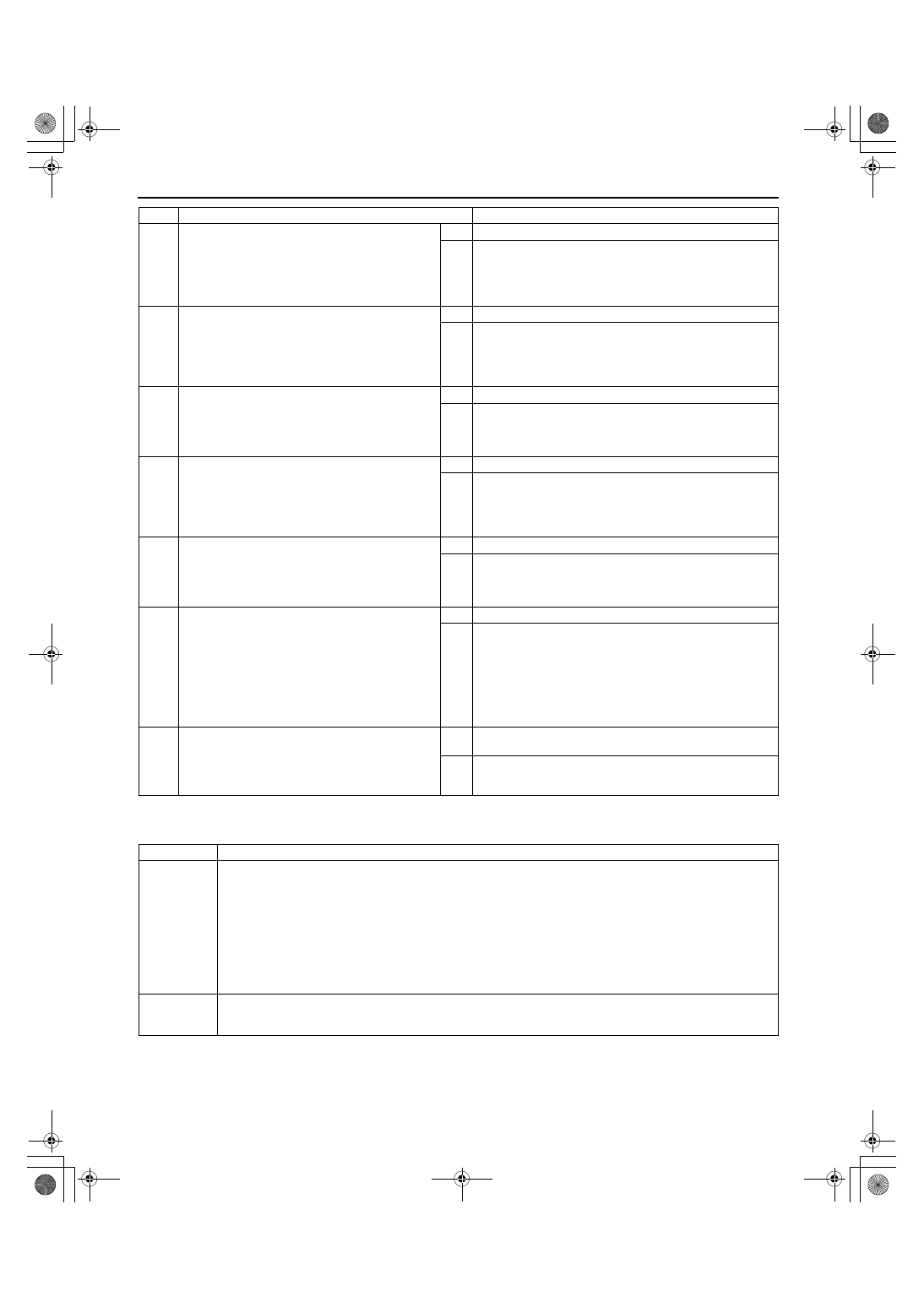
DTC P0125 [ZM]
A3U010201084W45
4
INSPECT TP SENSOR CONNECTOR FOR
POOR CONNECTION
•
Disconnect TP sensor connector.
•
Check for poor connection (damaged/pulled-
out terminals, corrosion, etc.).
•
Is there any malfunction?
Yes Repair or replace suspected terminal, then go to Step 9.
No
Go to next step.
5
CHECK TP SENSOR RESISTANCE
•
Check resistance between following TP sensor
terminals (part-side):
Terminals A and B: Within 3.2—4.8 kilohms
Terminals B and C: Within 0.2—1.2 kilohms
•
Are both resistances within specifications?
Yes Go to next step.
No
Replace TP sensor, then go to Step 9.
6
VERIFY TP SENSOR GROUND CIRCUIT FOR
OPEN CIRCUIT AT TP SENSOR CONNECTOR
•
Check for continuity between TP sensor
terminal B (harness-side) and body ground.
•
Is there continuity?
Yes Go to Step 8.
No
Go to next step.
7
CHECK PCM CONNECTOR
•
Disconnect PCM connector.
•
Check for poor connection at terminals 89, 90
and 91 (damaged/pulled-out terminals,
corrosion, etc.).
•
Is there any malfunction?
Yes Repair terminal, then go to Step 9.
No
Repair or replace open circuit in wiring harness between
TP sensor terminal B and PCM connector terminal 91
(harness-side). Then, go to Step 9.
8
VERIFY TP SIGNAL CIRCUIT FOR SHORT TO
CONSTANT VOLTAGE CIRCUIT
•
Check for continuity between TP sensor
terminals A and C.
•
Is there continuity?
Yes Repair or replace suspected harness, then go to next step.
No
Go to next step.
9
VERIFY TROUBLESHOOTING OF DTC P0123
COMPLETED
•
Make sure to reconnect all disconnected
connectors.
•
Start engine.
•
Clear DTC from PCM memory using WDS or
equipment.
•
Race engine a few times.
•
Does the same DTC appear?
Yes Replace PCM, then go to next step.
No
Go to next step.
10
VERIFY AFTER REPAIR PROCEDURE
•
Perform “After Repair Procedure”.
(See 01–02A–10 AFTER REPAIR
PROCEDURE [ZM].)
•
Is there any DTC present?
Yes Go to applicable DTC inspection.
(See 01–02A–15 DTC TABLE [ZM].)
No
Troubleshooting completed.
STEP
INSPECTION
ACTION
DTC P0125
Excessive time to enter closed loop fuel control
DETECTION
CONDITION
•
PCM monitors ECT sensor signal at PCM terminal 38 after engine is started engine is cold. If ECT voltage
does not reach the expected temperature within specified period, PCM determines that it has taken an
excessive amount of time for the engine coolant temperature to reach the temperature necessary to start
closed-loop fuel control.
Diagnostic support note
•
This is a continuous monitor (CCM).
•
MIL illuminates if PCM detects the above malfunction condition in two consecutive drive cycles.
•
PENDING CODE is available if PCM detects the above malfunction condition during first drive cycle.
•
FREEZE FRAME DATA is available.
•
DTC is stored in PCM memory.
POSSIBLE
CAUSE
•
ECT sensor malfunction
•
Poor connection of connectors
•
PCM malfunction
1712-1U-01G(01-02A).fm 46 ページ 2001年6月29日 金曜日 午後2時20分