Mazda Protege 5. Manual - part 5
GENERAL INFORMATION
00–00–17
00–00
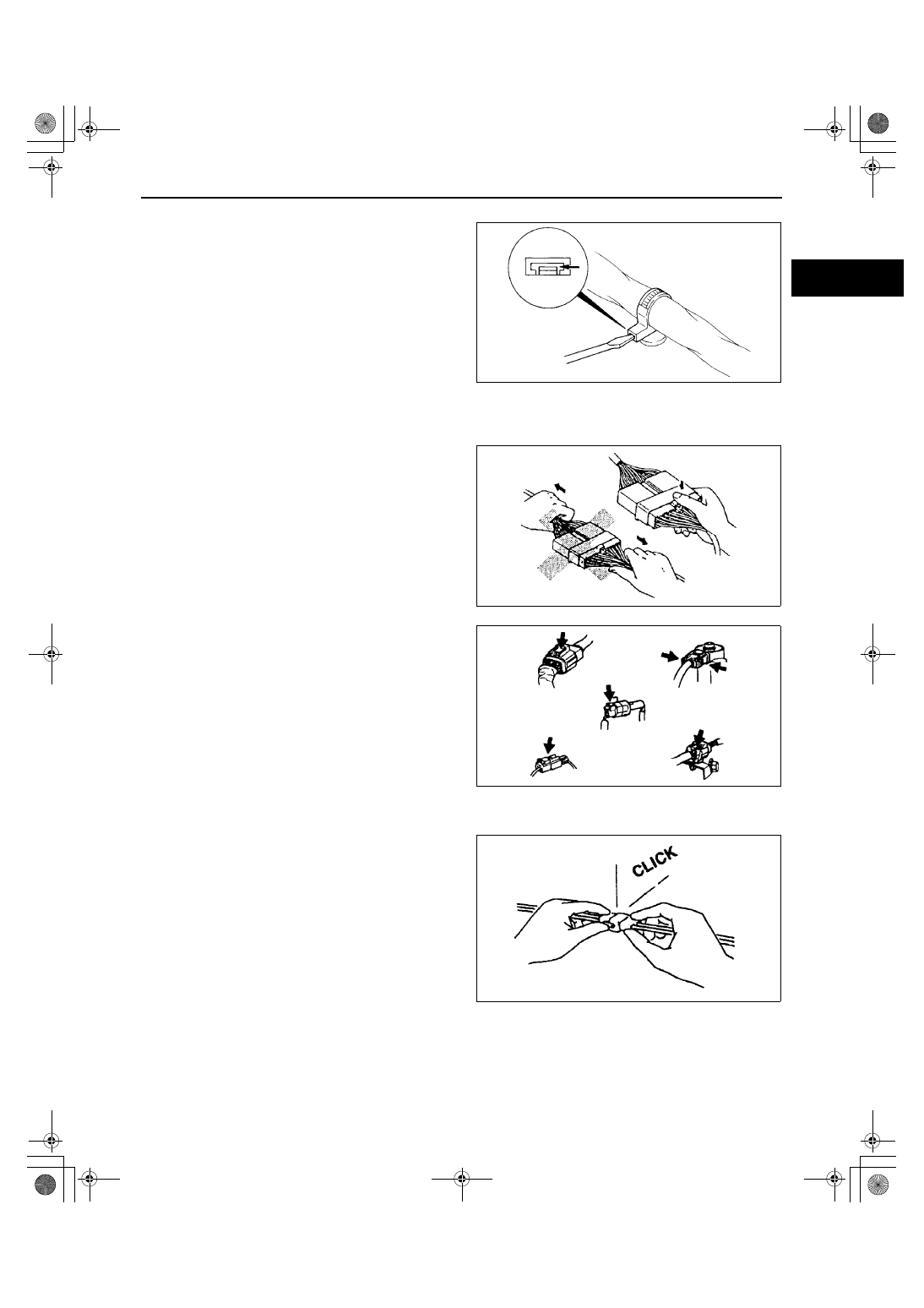
Wiring Harness
•
To remove the wiring harness from the clip in the
engine room, pry up the hook of the clip using a
flathead screwdriver.
Connectors
Disconnecting connectors
•
When disconnecting connector, grasp the
connectors, not the wires.
•
Connectors can be disconnected by pressing or
pulling the lock lever as shown.
Locking connector
•
When locking connectors, listen for a click
indicating they are securely locked.
WGIWXX0039E
WGIWXX0041E
WGIWXX0042E
WGIWXX0043E