Mazda MX-5 Miata (1997+). Manual - part 10


  Index      Mazda     Mazda MX-5 Miata - service repair manual 1997 year


Search            


Content   ..  8  9  10  11   ..


Mazda MX-5 Miata (1997+). Manual - part 10


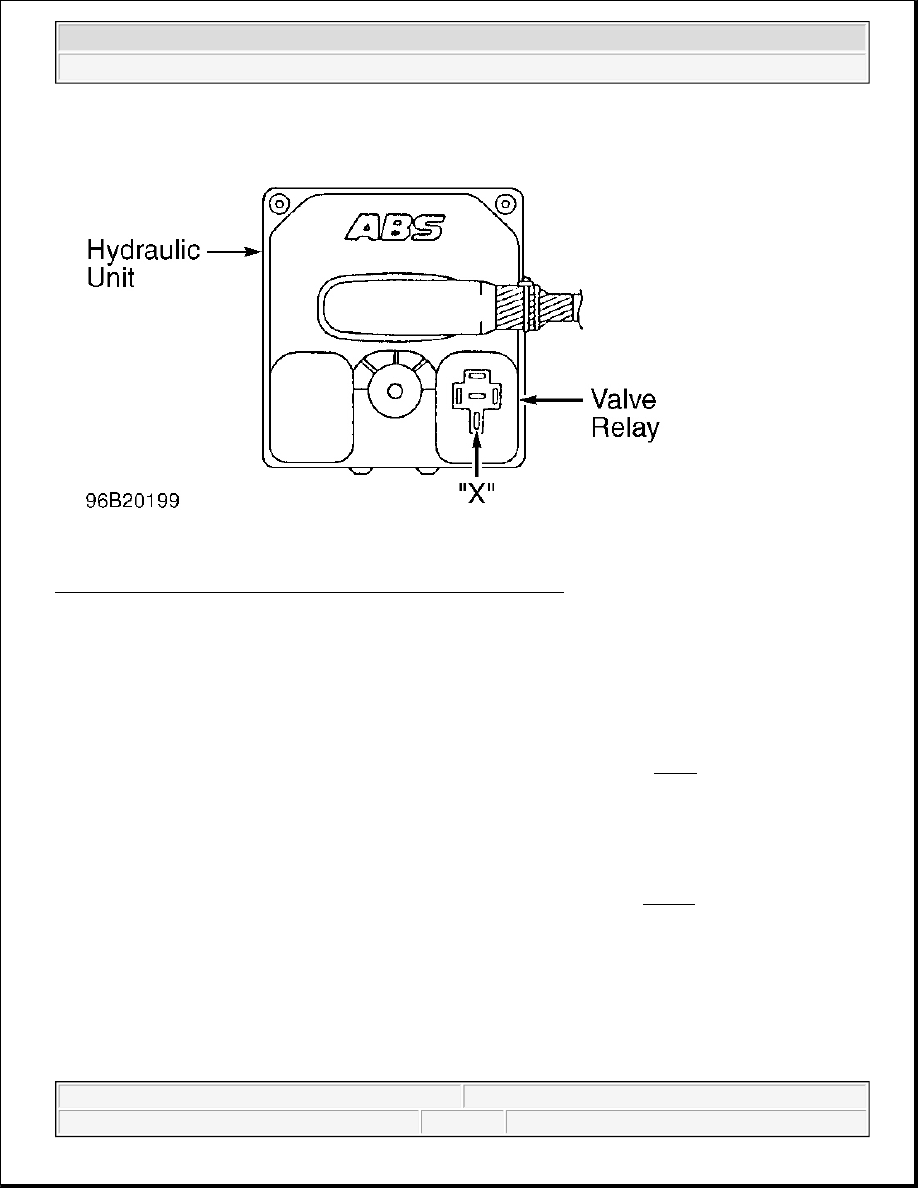
Fig. 9: Locating Hydraulic Unit Valve Relay Connector Terminals 
Courtesy of MAZDA MOTORS CORP. 

ABS WARNING LIGHT 

Operational Test 

1. Start engine and observe ABS warning light. Light should illuminate for a few seconds. If light does not 

illuminate as described, turn ignition off. Disconnect ABS control module connector. Using a jumper 
wire, connect terminal AD of ABS control module connector to ground. See Fig. 3 . Turn ignition on.  

2. If ABS warning light illuminates, check ABS control module. See ABS CONTROL MODULE. If light 

does not illuminate, remove instrument cluster. Remove and check ABS warning light bulb. Replace bulb 
as necessary. If bulb is okay, check METER fuse and wiring harness. Repair or replace as necessary. If 
METER fuse and wiring harness are okay, go to next step.  

3. Using ohmmeter, connect positive lead to terminal 2K (Black/Yellow wire) of instrument cluster and 

negative lead to terminal 1K (Blue/Yellow wire) of instrument cluster. See Fig. 10 . If continuity is not 
present, replace instrument cluster. If continuity is present, repair wiring harness between instrument 
cluster and ABS control module.  


1997 Mazda MX-5 Miata 

ANTI-LOCK BRAKE SYSTEM 1997 BRAKES Mazda - Anti-Lock


Fig. 10: Identifying Instrument Cluster Connector Terminals 
Courtesy of MAZDA MOTORS CORP. 

STOPLIGHT SWITCH 

Disconnect stoplight switch connector. Using ohmmeter, check continuity between stoplight switch terminals. 
With brake pedal depressed, continuity should exist. With brake pedal released, continuity should not exist. If 
continuity is not as specified, replace stoplight switch. 

MOTOR RELAY 

1. Turn ignition off. Disconnect ABS Control Module (ABS CM) connector. See COMPONENT 

LOCATIONS . Connect Adapter Harness (49-F066-002) to ABS CM connector. Turn ignition on. Using 
voltmeter, measure voltage between terminals "X" and AB of ABS CM connector. See Fig. 3 . Voltage 
should be zero volts. Apply 12 volts to terminal "B" an d ground terminal "G" of ABS CM connector. 
Using voltmeter, measure voltage between terminals "X" and AB of ABS CM connector. Voltage should 
be 12 volts. If voltage is not as specified, check wiring harness. If wiring harness is okay, go to next step. 

2. Remove motor relay from hydraulic unit. See Fig. 14 . Using ohmmeter, check continuity between 

terminals "B" and "C" of motor relay. See Fig. 11 . Continuity should exist. Apply 12 volts to terminal 
"C" and ground terminal "B". Using ohmmeter, check continuity between terminals "A" and "D" of motor 
relay. Continuity should exist. If continuity is not as specified, replace motor relay.  


1997 Mazda MX-5 Miata 

ANTI-LOCK BRAKE SYSTEM 1997 BRAKES Mazda - Anti-Lock


Fig. 11: Identifying Motor Relay Terminals 
Courtesy of MAZDA MOTORS CORP. 

VALVE RELAY 

1. Turn ignition off. Disconnect ABS Control Module (ABS CM) connector. See COMPONENT 

LOCATIONS . Connect Adapter Harness (49-F066-002) to ABS CM connector. Turn ignition on. Using 
voltmeter, measure voltage between terminal AB and terminals "E", "Z", "Y", AG, BA and BB of ABS 
CM connector. See Fig. 3 . Voltage on all terminals should be zero volts. If voltage is as specified, go to 
next step. If voltage is not as specified, check wiring harness and repair as necessary. If wiring harness is 
okay, go to step 3).  

2. Apply 12 volts to terminal "B" and ground terminal AK of ABS CM connector. Using voltmeter, measure 

voltage between terminal AB and terminals "E", "Z", "Y", AG, BA and BB of ABS CM connector. See 
Fig. 3 . Voltage on all terminals should be 12 volts. If voltage is not as specified, check wiring harness. If 
wiring harness is okay, go to next step.  

3. Remove valve relay from hydraulic unit. See Fig. 14 . Using ohmmeter, check continuity between 

terminals "B" and "C" of valve relay. See Fig. 12 . Continuity should exist. Apply 12 volts to terminal 
"B" and ground terminal "C". Using ohmmeter, check continuity between terminals "A" and "D" of valve 
relay. Continuity should exist. If continuity is not as specified, replace valve relay.  


1997 Mazda MX-5 Miata 

ANTI-LOCK BRAKE SYSTEM 1997 BRAKES Mazda - Anti-Lock


Fig. 12: Identifying Valve Relay Terminals 
Courtesy of MAZDA MOTORS CORP. 

WHEEL SPEED SENSORS 

On-Vehicle Inspection 

Remove wheel. Inspect wheel speed sensor for looseness and damage. Replace as necessary. Measure clearance 
between wheel speed sensor and sensor rotor. See Fig. 13 . Clearance should be .012-.043" (.3-1.1 mm). If 
clearance is not as specified, replace wheel speed sensor or sensor rotor. 

Resistance Test 

Disconnect wheel speed sensor connector. Using ohmmeter, measure resistance between wheel speed sensor 
terminals. Resistance should be 800-1200 ohms. If resistance is not as specified, replace wheel speed sensor. 

Voltage Test 

Ensure vehicle is on level surface. Raise and support vehicle on safety stands. Disconnect wheel speed sensor 
connector. Using voltmeter, while rotating wheel one revolution per second, measure voltage between wheel 
speed sensor terminals. Voltage should be .25-1.2 volts (AC). If voltage is not as specified, replace wheel speed 


1997 Mazda MX-5 Miata 

ANTI-LOCK BRAKE SYSTEM 1997 BRAKES Mazda - Anti-Lock


Content   ..  8  9  10  11   ..