Mazda MX-5 Miata (1997+). Manual - part 9


  Index      Mazda     Mazda MX-5 Miata - service repair manual 1997 year


Search            


Content   ..  7  8  9  10   ..


Mazda MX-5 Miata (1997+). Manual - part 9


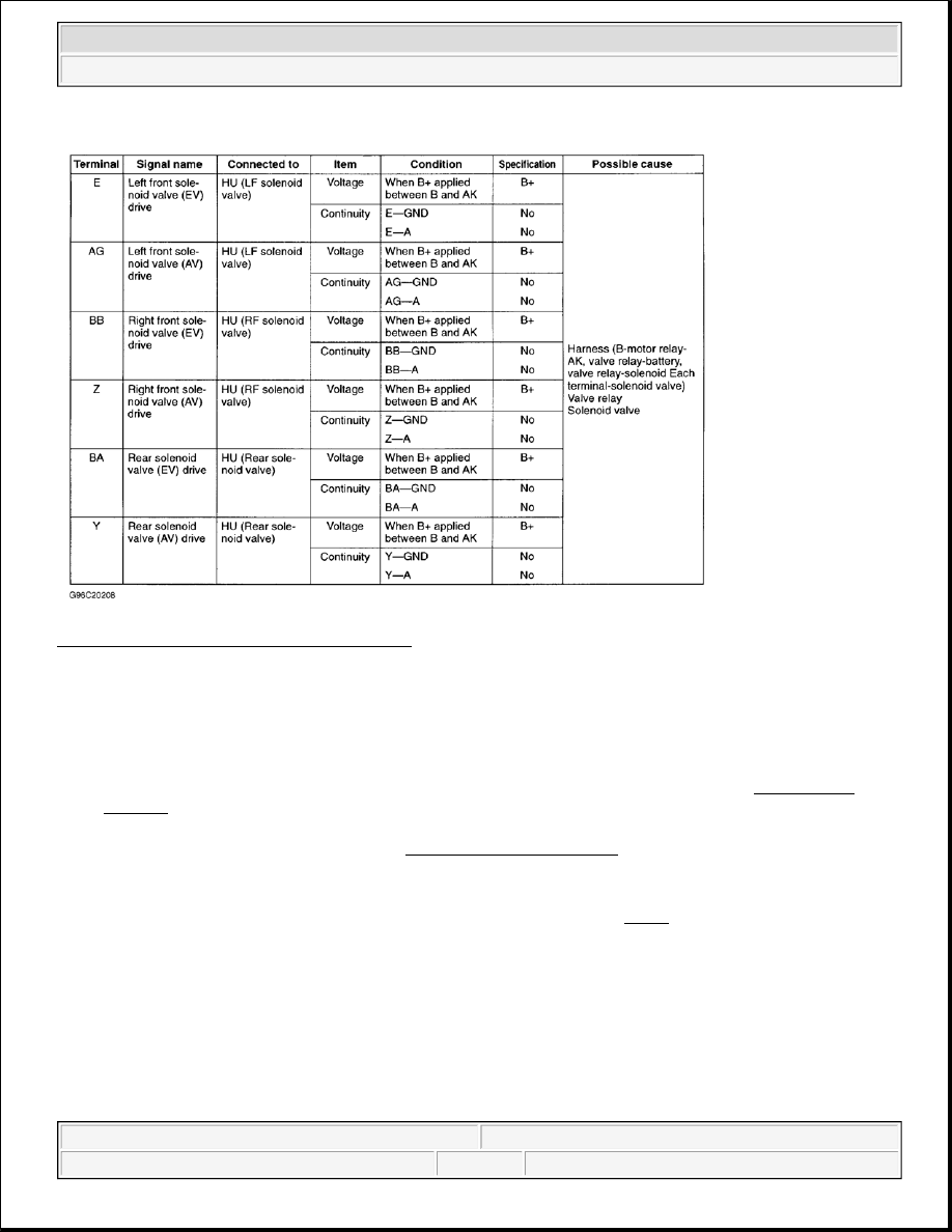
Fig. 6: Testing ABS Control Module (3 Of 3) 
Courtesy of MAZDA MOTORS CORP. 

HYDRAULIC UNIT 

On-Vehicle Inspection 

1. Ensure all diagnostic trouble codes have been cleared and battery is fully charged. See CLEARING 

CODES under DIAGNOSIS & TESTING. Turn ignition on and check if ABS warning light goes out 
after 2-4 seconds. If ABS warning light remains illuminated, ABS control module has detected a failure 
and will not activate hydraulic unit. See DIAGNOSIS & TESTING .  

2. Turn ignition off. Ensure vehicle is on level surface. Raise and support vehicle. Place transmission in 

Neutral. Release parking brake. Rotate wheels by hand and check for brake drag. Connect a jumper wire 
between TBS terminal and GND terminal of data link connector. See Fig. 1 . Depress brake pedal and 
have an assistant attempt to rotate right front wheel. Wheel should not rotate.  

3. With brake pedal still depressed, turn ignition on. Brake should be momentarily released (about .5 

second) and wheel should turn when pressure reduction operates. Check operation of remaining wheels 
using same procedure beginning with left front, right rear, then left rear wheels.  

4. If all wheels operate as specified, the following systems are operating properly. 

Brake piping to hydraulic unit.  

Braking system, including hydraulic unit.  

Hydraulic unit electrical system (solenoid, pump motor, etc.) 


1997 Mazda MX-5 Miata 

ANTI-LOCK BRAKE SYSTEM 1997 BRAKES Mazda - Anti-Lock


ABS control module output system (solenoid, relay, etc.) and harness.  

5. If all wheels do not operate as specified, check ABS control module input system and wiring harness for 

intermittent failure. Check for fluid leakage. Repair as necessary. If input system, wiring harness, 
intermittent failure or fluid leakage are not present, replace hydraulic unit.  

PUMP MOTOR 

1. Turn ignition off. Disconnect ABS Control Module (ABS CM) connector. See COMPONENT 

LOCATIONS . Connect Adapter Harness (49-F066-002) to ABS CM connector. Using ohmmeter, 
measure resistance between terminal "X" of ABS CM connector and ground. See Fig. 3 . Resistance 
should not be more than one ohm. If the resistance is not as specified, check wiring harness between ABS 
CM and pump motor. Refer to WIRING DIAGRAMS . If wiring harness is okay, go to next step.  

2. Turn ignition off. Disconnect pump motor/hydraulic unit 2-pin connector. Using ohmmeter, measure 

resistance between terminal "B" of pump motor/hydraulic unit connector and ground. See Fig. 7 . 
Resistance should not be more than one ohm. Apply 12 volts across pump motor/hydraulic unit 2-pin 
connector terminals. Pump motor should operate. If resistance is not as specified or pump motor does not 
operate, check wiring harness. If wiring harness is okay, replace hydraulic unit.  

Fig. 7: Identifying Pump Motor/Hydraulic Unit Connector Terminals 
Courtesy of MAZDA MOTORS CORP. 

SOLENOID VALVES 

With Valve Relay Installed 

Turn ignition off. Disconnect hydraulic unit 12-pin connector. See COMPONENT LOCATIONS . Apply 12 


1997 Mazda MX-5 Miata 

ANTI-LOCK BRAKE SYSTEM 1997 BRAKES Mazda - Anti-Lock


volts to terminal "A" and ground terminal "D" of hydraulic unit 12-pin connector. See Fig. 8 . Using ohmmeter, 
measure resistance between terminal "B" and specified terminals of hydraulic unit connector. See 
HYDRAULIC UNIT CONNECTOR TERMINAL RESISTANCE table. If resistance is not as specified, 
check solenoid valves with vale relay removed. See WITH VALVE RELAY REMOVED. Also check valve 
relay. See VALVE RELAY. 

HYDRAULIC UNIT CONNECTOR TERMINAL RESISTANCE 

With Valve Relay Removed 

Turn ignition off. Remove hydraulic unit. See HYDRAULIC UNIT under REMOVAL & INSTALLATION . 
Remove valve relay from hydraulic unit. Using ohmmeter, measure resistance between terminal "X" of 
hydraulic unit valve relay connector and specified terminals of hydraulic unit connector. See Fig. 8 and Fig. 9 . 
See HYDRAULIC UNIT CONNECTOR TERMINAL RESISTANCE table. If resistance is not as specified, 
check wiring harness. If wiring harness is okay, replace hydraulic unit.

Terminal

Ohms

"H"

4.7

"I"

4.7

"J"

4.7

"M"

9

"N"

9

"O"

9


1997 Mazda MX-5 Miata 

ANTI-LOCK BRAKE SYSTEM 1997 BRAKES Mazda - Anti-Lock


Fig. 8: Identifying Hydraulic Unit Connector Terminals 
Courtesy of MAZDA MOTORS CORP. 


1997 Mazda MX-5 Miata 

ANTI-LOCK BRAKE SYSTEM 1997 BRAKES Mazda - Anti-Lock


Content   ..  7  8  9  10   ..