Mazda 5. Manual - part 70


  Index      Mazda     Mazda 5 - service repair manual


Search            


Content   ..  68  69  70  71   ..


Mazda 5. Manual - part 70


BODY STRUCTURE [PANEL REPLACEMENT]

09–80B–43

09

End Of Sie

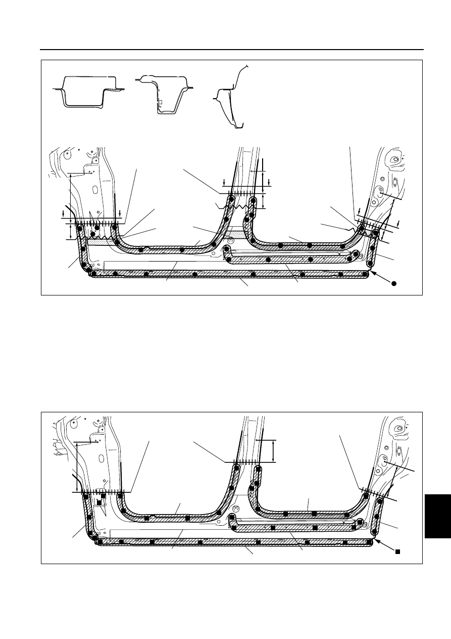
SIDE SILL PANEL (OUTER) INSTALLATION

DPE098070270B02

1. When joining and cutting the new and existing parts, trial fit the new part in position, and then measure and 

adjust the body as necessary to conform with standard dimensions.

2. Drill holes for plug welds before installing new parts.

Note

• The shape for the right side is different. In areas where the outer, reinforcement, inner, and other parts are 

in 3-4 layers, drill holes for plug welds in all but the innermost panel.

3. Before installing new parts, apply spot weld sealer to the tire arch line.
4. After temporarily installing new parts, make sure the related parts fit properly.

End Of Sie

INSULATOR

INSULATOR

160mm

{6.30in}

50mm

{1.97in}

110mm

345mm

{13.58in}

{4.33in}

240 mm

{9.45in}

50mm
{1.97in}

2

3

20

41

11

25

2

10

B

B

A

C

C

A

C-C

A-A

B-B

CUT-AND-JOIN 
LOCATION (OUTER)

CUT-AND-JOIN 
LOCATION (OUTER)

SIDE SILL PANEL (OUTER)

ROUGH CUT LOCATION
(OUTER)

ROUGH CUT LOCATION 
(OUTER)

DPE0980B091

160mm

345mm

240 mm

2

5

20

41

11

25

2

10

 SIDE SILL PANEL (OUTER)

CUT-AND-JOIN 
LOCATION (OUTER)

CUT-AND-JOIN 
LOCATION (OUTER)

{13.58in}

{9.45in}

{6.30in}

DPE0980B092

09–80B–44

BODY STRUCTURE [PANEL REPLACEMENT]

SIDE SILL REINFORCEMENT REMOVAL

DPE098070270B03

Caution

• The side sill reinforcement removal procedure is based on the condition that the center pillar 

(outer) and the center pillar reinforcement have been removed.

1. Rough cut area (A), drill the 9 locations indicated by (B), and then remove the side sill reinforcement.

End Of Sie

SIDE SILL REINFORCEMENT INSTALLATION

DPE098070270B04

Caution

• The side sill reinforcement removal procedure is based on the condition that the center pillar 

(outer) and the center pillar reinforcement have been removed.

1. When joining and cutting the new and existing parts, trial fit the new part in position, and then measure and 

adjust the body as necessary to conform with standard dimensions.

2. Drill holes for plug welds before installing new parts.
3. After temporarily installing new parts, make sure the related parts fit properly.

End Of Sie

REAR FENDER PANEL REMOVAL

DPE098074100B01

Caution

• Avoid cutting with a blow torch or similar tools as the insulator (shaded area) is flammable.

(B)9

210mm

{8.27in}

50mm

{1.97in}

(A)

CUT-AND-JOIN LOCATION FOR SIDE 
SILL REINFORCEMENT

ROUGH CUT LOCATION FOR 
SIDE SILL REINFORCEMENT

 SIDE SILL REINFORCEMENT

DPE0980B093

9

210mm

CUT-AND-JOIN LOCATION FOR SIDE 
SILL REINFORCEMENT

{8.27in}

 SIDE SILL REINFORCEMENT

DPE0980B094

BODY STRUCTURE [PANEL REPLACEMENT]

09–80B–45

09

1. The rear fender panel and the rear pillar (inner) are joined with spot weld sealer at the tire arch line. Use a 

chisel or similar tool to separate the rear fender panel from the rear pillar (inner), then remove the rear fender 
panel.

2. Remove the spot weld sealer using a disc grinder.

End Of Sie

REAR FENDER PANEL INSTALLATION

DPE098074100B02

1. When joining and cutting the new and existing parts, trial fit the new part in position, and then measure and 

adjust the body as necessary to conform with standard dimensions.

2. Drill holes for plug welds before installing new parts.
3. Before installing new parts, apply spot weld sealer to the tire arch line.
4. After temporarily installing new parts, make sure the related parts fit properly.

40mm

{1.57in}

{1.57in}

40mm

70mm

{2.76in}

65mm

{2.56in}

50mm

{1.97in}

240mm

{9.45in}

2

14

16

15

1

16

10

4

A

B

B

A

C

C

A-A

B-B

C-C

CUT-AND-JOIN LOCATION 
FOR REAR FENDER PANEL

CUT-AND-JOIN LOCATION 
FOR  REAR FENDER 
PANEL

CUT-AND-JOIN LOCATION FOR  
REAR FENDER PANEL

REAR FENDER PANEL

ROUGH CUT LOCATION 
FOR REAR FENDER PANEL

ROUGH CUT LOCATION 
FOR REAR FENDER 
PANEL

ROUGH CUT LOCATION FOR 
REAR FENDER PANEL

INSULATOR

DPE0980B089

09–80B–46

BODY STRUCTURE [PANEL REPLACEMENT]

End Of Sie

C-PILLAR REINFORCEMENT REMOVAL

DPE098074100B03

1. Remove the C-pillar reinforcement.

70mm

65mm

290mm

{11.42in}

16

1

16

13

5

2

14

16

CUT-AND-JOIN LOCATION 
FOR REAR FENDER PANEL

CUT-AND-JOIN LOCATION 
FOR REAR FENDER PANEL

CUT-AND-JOIN LOCATION 
FOR REAR FENDER PANEL

REAR FENDER PANEL

{2.56in}

{2.76in}

DPE0980B090


Content   ..  68  69  70  71   ..