Mazda 5. Manual - part 67


  Index      Mazda     Mazda 5 - service repair manual


Search            


Content   ..  65  66  67  68   ..


Mazda 5. Manual - part 67


BODY STRUCTURE [PANEL REPLACEMENT]

09–80B–31

09

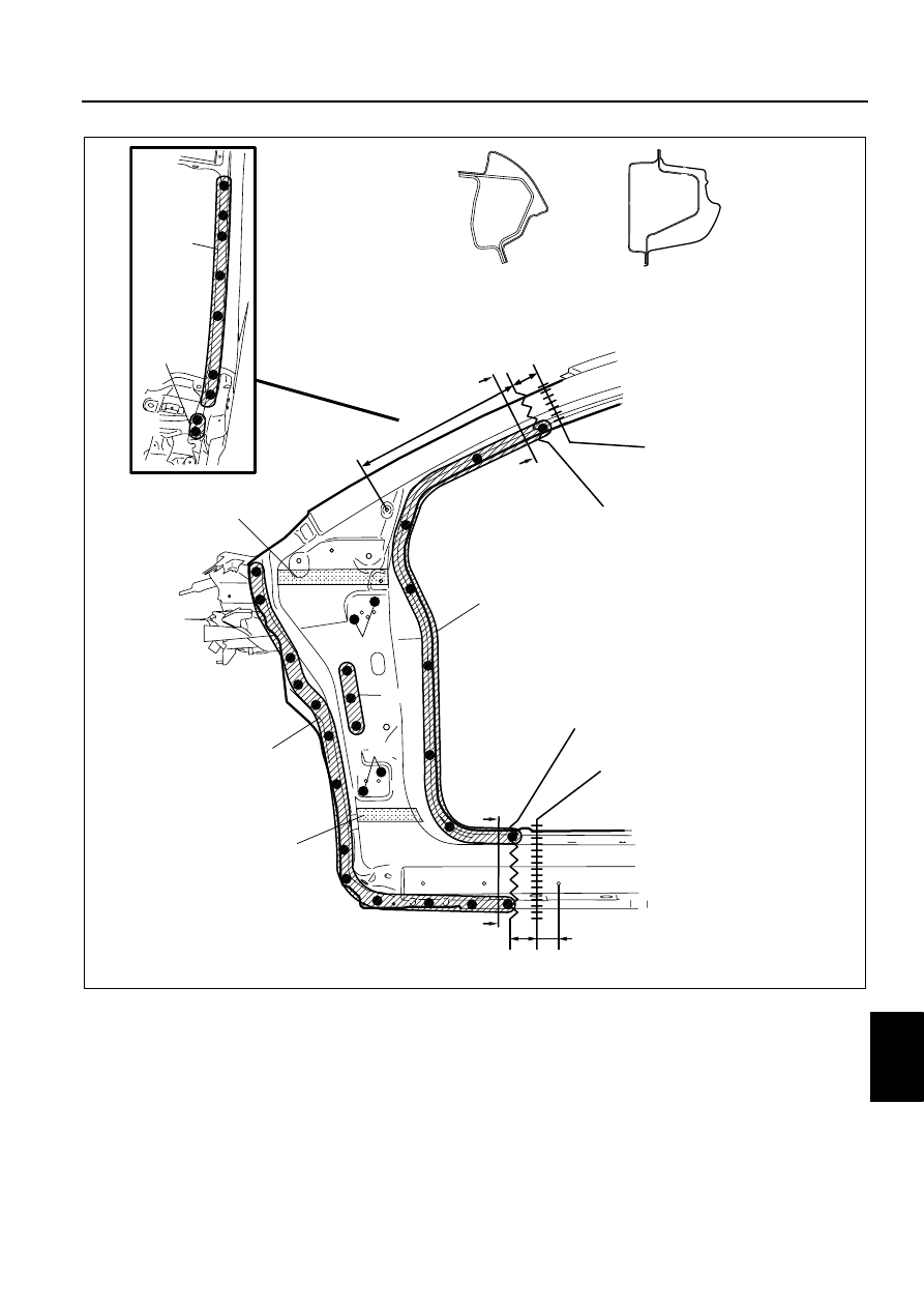
3. Remove the front pillar (outer).

4. Rough cut area (D) and drill the 5 locations indicated by (E).
5. Drill the 6 locations indicated by (F) from the interior.
6. Remove the bolt from the locations indicated by (A).
7. Remove the front pillar reinforcement.

Note

• When removing the front pillar reinforcement (upper) and the front pillar reinforcement (rear) separately, 

drill the 10 locations indicated by (H).

(B)12

(C)2

90mm 

55mm

{2.17in}

{3.54in}

(B)25

(B)27

(B)2

(B)2

(B)3

430mm

{16.93in}

50mm {1.97in}

INSULATOR

INSULATOR

(A)

(A)

A

A

A-A

B-B

B                     

B

CUT-AND-JOIN  LOCATION 
FOR FRONT PILLAR 
(OUTER)

CUT-AND-JOIN  LOCATION 
FOR FRONT PILLAR 
(OUTER)

ROUGH CUT LOCATION FOR  
FRONT PILLAR (OUTER)

ROUGH CUT LOCATION FOR  
FRONT PILLAR (OUTER)

DPE0980B077

09–80B–32

BODY STRUCTURE [PANEL REPLACEMENT]

8. Rough cut area (I) and remove the side sill reinforcement (front).

(E)1

(H)10

(E)4

35mm

{1.38in}

45mm

{1.77in}

(D)

(I)

(F)3

(G)1

80mm {3.15in}

{1.57in}

40mm

(                        

CUT-AND-JOIN  LOCATION FOR FRONT 
PILLAR REINFORCEMENT (UPPER)

 FRONT PILLAR REINFORCEMENT 
(UPPER)

ROUGH CUT LOCATION FOR 
FRONT PILLAR REINFORCEMENT 
(UPPER)                 

 FRONT PILLAR REINFORCEMENT 
(LOWER)

SIDE SILL 
REINFORCEMENT (FRONT)

CUT-AND-JOIN  LOCATION FOR SIDE 
SILL REINFORCEMENT (FRONT)

ROUGH CUT LOCATION FOR SIDE 
SILL REINFORCEMENT (FRONT)

DPE0980B078

BODY STRUCTURE [PANEL REPLACEMENT]

09–80B–33

09

9. Rough cut area (J), drill the location indicated by (K), and then remove the front pillar (inner).

End Of Sie

FRONT PILLAR INSTALLATION

DPE098074090B02

1. When joining and cutting the new and existing parts, trial fit the new part in position, and then measure and 

adjust the body as necessary to conform with standard dimensions.

2. Drill holes for plug welds before installing new parts.

Note

• The shape for the right side is different. In areas where the outer, reinforcement, inner, and other parts are 

in 3-4 layers, drill holes for plug welds in all but the innermost panel.

(K)1

(J)

50mm

{1.97in}

110mm

{4.33in}

 FRONT PILLAR (INNER)

CUT-AND-JOIN  LOCATION FOR 
FRONT PILLAR (INNER)

ROUGH CUT LOCATION FOR 
FRONT PILLAR (INNER)

DPE0980B079

09–80B–34

BODY STRUCTURE [PANEL REPLACEMENT]

3. Make a reinforcement panel using the material from the front pillar reinforcement.
4. To cut and join the new and existing parts, cut the new part at the specified location shown in the figure, and 

chamfer the joint surfaces of the new and existing parts.

5. Because the front pillar reinforcement cannot be welded to the existing parts from the inside of the inner, drill 4 

plug weld holes at the locations indicated by (A) on the existing parts. Install the reinforcement and the existing 
parts by plug welding from the outside, then butt weld the new and existing parts.

Caution

• Press fit the reinforcement panel and the body side material, and then plug weld them.

6. Grind the butt welded area with a disc grinder to finish the surface.
7. Install the bolt to the locations indicated by (B).
8. Weld the 9 locations indicated by (C) and install the front pillar reinforcement.

1

110mm

{4.33in}

CUT-AND-JOIN  LOCATION FOR 
FRONT PILLAR (INNER)

 FRONT PILLAR (INNER)

DPE0980B082


Content   ..  65  66  67  68   ..