Mazda 5. Manual - part 18
GENERAL INFORMATION
00–00–3
00
Advisory Messages
• You will find several Warnings, Cautions, Notes, Specifications and Upper and Lower Limits in this
manual.
Warning
• A Warning indicates a situation in which serious injury or death could result if the warning is ignored.
Caution
• A Caution indicates a situation in which damage to the vehicle or parts could result if the caution is ignored.
Note
• A Note provides added information that will help you to complete a particular procedure.
Specification
• The values indicate the allowable range when performing inspections or adjustments.
Upper and lower limits
• The values indicate the upper and lower limits that must not be exceeded when performing inspections or
adjustments.
End Of Sie
UNITS
B3E000000002A01
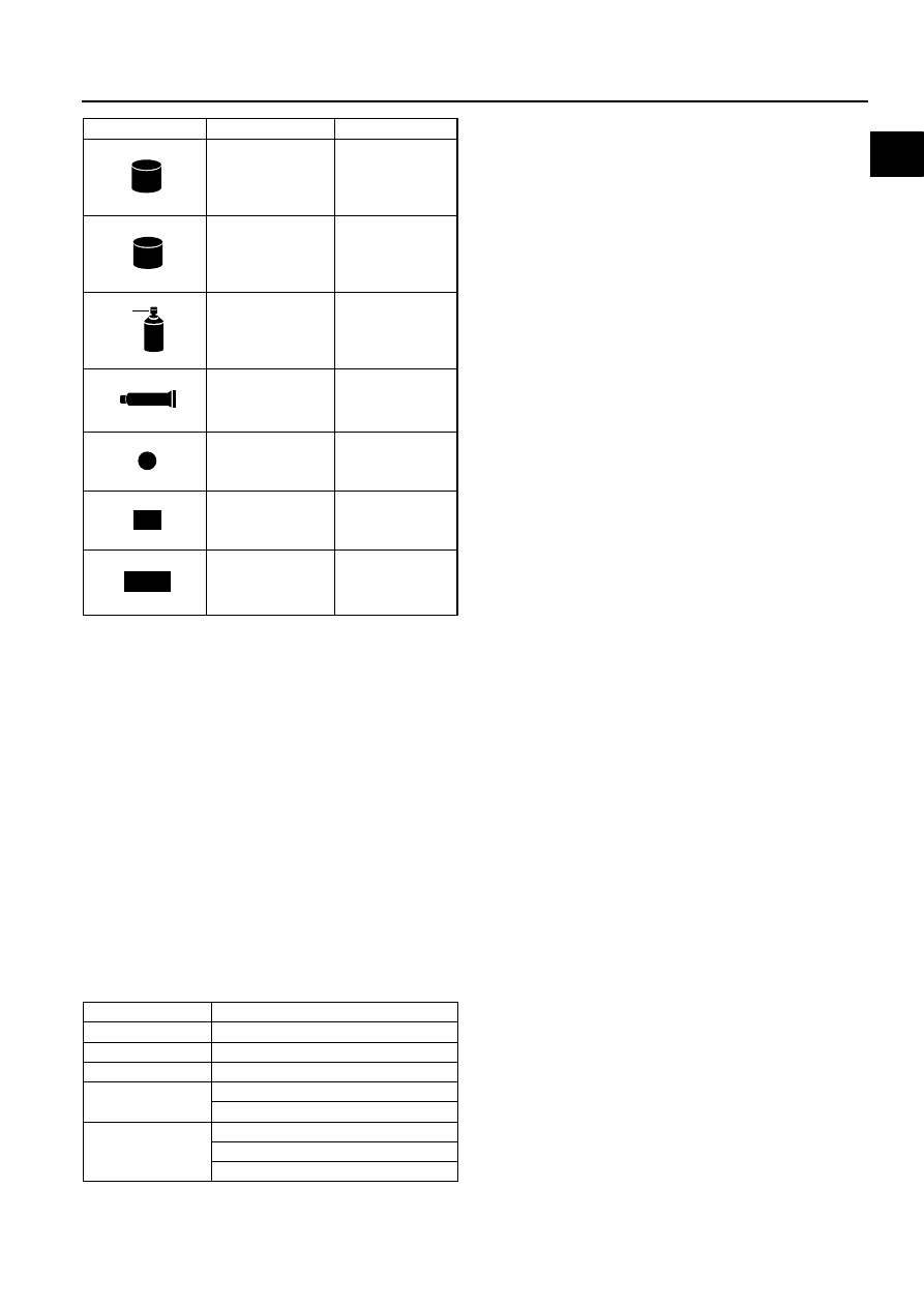
Apply brake fluid
New appropriate
brake fluid
Apply automatic
transaxle/
transmission fluid
New appropriate
automatic
transaxle/
transmission fluid
Apply grease
Appropriate
grease
Apply sealant
Appropriate
sealant
Apply petroleum
jelly
Appropriate
petroleum jelly
Replace part
O-ring, gasket,
etc.
Use SST or
equivalent
Appropriate tools
Symbol
Meaning
Kind
BRAKE
BRAKE
FLUID
A
ATF
TF
GREASEGREASE
SEALANT
P
R
SST
Electric current
A (ampere)
Electric power
W (watt)
Electric resistance
ohm
Electric voltage
V (volt)
Length
mm (millimeter)
in (inch)
Negative pressure
kPa (kilo pascal)
mmHg (millimeters of mercury)
inHg (inches of mercury)