Mazda 5. Manual - part 3


  Index      Mazda     Mazda 5 - service repair manual


Search            


Content   ..  1  2  3  4  ..


Mazda 5. Manual - part 3


GENERAL INFORMATION 

00–00–9

00

End Of Sie

NEW STANDARDS

B3E000000003201

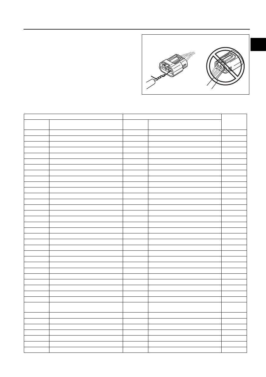
• Following is a comparison of the previous standard and the new standard.

GOOD

NO GOOD

CHU0000W012

New Standard

Previous Standard

Remark

Abbrevi-

ation

Name

Abbrevi-
ation

Name

AP

Accelerator Pedal

Accelerator Pedal

ACL

Air Cleaner

Air Cleaner

A/C

Air Conditioning

Air Conditioning

BARO

Barometric Pressure

Atmospheric Pressure

B+

Battery Positive Voltage

Vb

Battery Voltage

Brake Switch

Stoplight Switch

Calibration Resistor

Corrected Resistance

#6

CMP sensor Camshaft Position Sensor

Crank Angle Sensor

CAC

Charge Air Cooler

Intercooler

CLS

Closed Loop System

Feedback System

CTP

Closed Throttle Position

Fully Closed

CPP

Clutch Pedal Position

Idle Switch

CIS

Continuous Fuel Injection System

Clutch Position

CS sensor

Control Sleeve Sensor

CSP  sensor Control Sleeve Position Sensor

#6

CKP sensor Crankshaft Position Sensor

Crank Angle Sensor 2

DLC

Data Link Connector

Diagnosis Connector

DTM

Diagnostic Test Mode

Test Mode

#1

DTC

Diagnostic Trouble Code(s)

Service Code(s)

DI

Distributor Ignition

Spark Ignition

DLI

Distributorless Ignition

Direct Ignition

EI

Electronic Ignition

Electronic Spark Ignition

#2

ECT

Engine Coolant Temperature

Water Thermo

EM

Engine Modification

Engine Modification

Engine Speed Input Signal

Engine RPM Signal

EVAP

Evaporative Emission

Evaporative Emission

EGR

Exhaust Gas Recirculation

Exhaust Gas Recirculation

FC

Fan Control

Fan Control

FF

Flexible Fuel

Flexible Fuel

4GR

Fourth Gear

Overdrive

Fuel Pump Relay

Circuit Opening Relay

#3

FSO 

solenoid

Fuel Shut Off Solenoid

FCV

Fuel Cut Valve

#6

GEN

Generator

Alternator

GND

Ground

Ground/Earth

HO2S

Heated Oxygen Sensor

Oxygen Sensor

With heater

IAC

Idle Air control

Idle Speed Control

IDM Relay

Spill Valve Relay

#6

Incorrect Gear Ratio

Injection Pump

FIP

Fuel Injection Pump

#6

00–00–10

GENERAL INFORMATION 

#1 : Diagnostic trouble codes depend on the diagnostic test mode
#2 : Controlled by the PCM
#3 : In some models, there is a fuel pump relay that controls pump speed.  That relay is now called the fuel pump 

relay (speed).

#4 : Device that controls engine and powertrain
#5 : Directly connected to exhaust manifold

Input/Turbine Speed Sensor

Pulse Generator

IAT

Intake Air Temperature

Intake Air Thermo

KS

Knock Sensor

Knock Sensor

MIL

Malfunction Indicator Lamp

Malfunction Indicator Light

MAP

Manifold Absolute Pressure

Intake Air Pressure

MAF sensor Mass Air Flow Sensor

Airflow Sensor

MFL

Multiport Fuel Injection

Multiport Fuel Injection

OBD

On-Board Diagnostic

Diagnosis/Self-Diagnosis

OL

Open Loop

Open Loop

Output Speed Sensor

Vehicle Speed Sensor 1

OC

Oxidation Catalytic Converter

Catalytic Converter

O2S

Oxygen Sensor

Oxygen Sensor

PNP

Park/Neutral Position

Park/Neutral Range

PCM Control Relay

Main Relay

#6

PSP

Power Steering Pressure

Power Steering Pressure

PCM

Powertrain Control Module

ECU

Engine Control Unit

#4

Pressure Control Solenoid

Line Pressure Solenoid Valve

PAIR

Pulsed Secondary Air Injection

Secondary Air Injection System

Pulsed  
injection

Pump Speed Sensor

NE Sensor

#6

AIR

Secondary Air Injection

Secondary Air Injection System

Injection 
with air 
pump

SAPV

Secondary Air Pulse Valve

Reed Valve

SFI

Sequential Multipoint Fuel Injection

Sequential Fuel Injection

Shift Solenoid A

12 Shift Solenoid Valve

Shift A Solenoid Valve

Shift Solenoid B

23 Shift Solenoid Valve

Shift B Solenoid Valve

Shift Solenoid C

34 Shift Solenoid Valve

3GR

Third Gear

3rd Gear

TWC

Three Way Catalytic Converter

Catalytic Converter

TB

Throttle Body

Throttle Body

TP sensor

Throttle Position Sensor

Throttle Sensor

TCV

Timer Control Valve

TCV

Timing Control Valve

#6

TCC

Torque Converter Clutch

Lockup Position

TCM

Transmission (Transaxle) Control 
Module

EC-AT Control Unit

Transmission (Transaxle) Fluid 
Temperature Sensor

ATF Thermosensor

TR

Transmission (Transaxle) Range

Inhibitor Position

TC

Turbocharger

Turbocharger

VSS

Vehicle Speed Sensor

Vehicle Speed Sensor 

VR

Voltage Regulator

IC Regulator

VAF sensor Volume Air Flow Sensor 

Air flow Sensor

WUTWC

Warm Up Three Way Catalytic 
Converter

Catalytic Converter

#5

WOT

Wide Open Throttle

Fully Open

New Standard

Previous Standard

Remark

Abbrevi-

ation

Name

Abbrevi-
ation

Name

GENERAL INFORMATION 

00–00–11

00

#6 : Part name of diesel engine

End Of Sie

ABBREVIATIONS

B3E000000011201

End Of Sie

ATDC

After Top Dead Center

ATX

Automatic Transaxle

EGR

Exhaust Gas Recirculation

EX

Exhaust

IN

Intake

MTX

Manual Transaxle

OCV

Oil Control Valve

TDC

Top Dead Center

SST

Special Service Tool

01–10–1

01

ENGINE

SECTION

01

Toc of SCT

MECHANICAL  . . . . . . . . . . . . .  01-10
TECHNICAL DATA. . . . . . . . . .  01-50

SERVICE TOOLS . . . . . . . . . . . 01-60

Toc of SCT

01–10

MECHANICAL

ENGINE OVERHAUL 

SERVICE WARNING . . . . . . . . . . . . . . .  01–10–1

ENGINE MOUNTING/DISMOUNTING  . .  01–10–1
TIMING CHAIN DISASSEMBLY . . . . . . .  01–10–3
CYLINDER HEAD (I) DISASSEMBLY. . .  01–10–5
CYLINDER HEAD (II) DISASSEMBLY . .  01–10–7
CYLINDER BLOCK (I) DISASSEMBLY  .  01–10–9
CYLINDER BLOCK (II) DISASSEMBLY . 01–10–10
CYLINDER HEAD INSPECTION. . . . . . .  01–10–11
VALVE, VALVE GUIDE INSPECTION . . .  01–10–12
VALVE GUIDE REPLACEMENT . . . . . . .  01–10–13
VALVE SEAT INSPECTION/REPAIR  . . .  01–10–14
VALVE SPRING INSPECTION  . . . . . . . .  01–10–15
CAMSHAFT INSPECTION  . . . . . . . . . . .  01–10–15
TAPPET INSPECTION  . . . . . . . . . . . . . .  01–10–17
CYLINDER BLOCK INSPECTION  . . . . .  01–10–17

OIL JET VALVE INSPECTION . . . . . . . . . 01–10–18
PISTON INSPECTION  . . . . . . . . . . . . . . . 01–10–18
CRANKSHAFT INSPECTION  . . . . . . . . . 01–10–19
CONNECTING ROD INSPECTION  . . . . . 01–10–21
BOLT INSPECTION . . . . . . . . . . . . . . . . . 01–10–21
VARIABLE VALVE TIMING ACTUATOR 

INSPECTION  . . . . . . . . . . . . . . . . . . . . . 01–10–22

OIL CONTROL VALVE (OCV) 

INSPECTION  . . . . . . . . . . . . . . . . . . . . . 01–10–22

VALVE CLEARANCE INSPECTION  . . . . 01–10–23
VALVE CLEARANCE ADJUSTMENT  . . . 01–10–24
CYLINDER BLOCK (I) ASSEMBLY . . . . . 01–10–27
CYLINDER BLOCK (II) ASSEMBLY  . . . . 01–10–33
CYLINDER HEAD (I) ASSEMBLY . . . . . . 01–10–36
CYLINDER HEAD (II) ASSEMBLY. . . . . . 01–10–37
TIMING CHAIN ASSEMBLY. . . . . . . . . . . 01–10–40

End of Toc

ENGINE OVERHAUL SERVICE WARNING

B3E011002000201

Warning

• Continuous exposure with USED engine oil has caused skin cancer in laboratory mice. Protect 

your skin by washing with soap and water immediately after this work.

End Of Sie

ENGINE MOUNTING/DISMOUNTING

B3E011002000202

1. Install the SSTs (arms) to the cylinder block holes 

as shown, and hand-tighten the bolts (part No.: 
9YA20-1003) or M10 

× 1.5T length 90 mm {3.55 

in}.

2. Assemble the SSTs (bolts, nuts and plate) to the 

specified positions.

3. Adjust the SSTs (bolts) so that less than 20 mm 

{0.79 in} of thread is exposed.

4. Make the SSTs (arms and plate) parallel by 

adjusting the SSTs (bolts and nuts).

49 L010 102

B3E0110W127

49 L010 101

49 L010 104

49 L010 105

ADJ2224E013


Content   ..  1  2  3  4  ..