Mazda X-5. Manual - part 72


  Index      Mazda     Mazda X-5 - service repair manual 2006 year


Search            


Content   ..  70  71  72  73   ..


Mazda X-5. Manual - part 72


MANUAL TRANSMISSION [M15M-D]

05–11A–7

05–11A

POWER PLANT FRAME (PPF) FUNCTION [M15M-D]

E5U051100000N21

Features

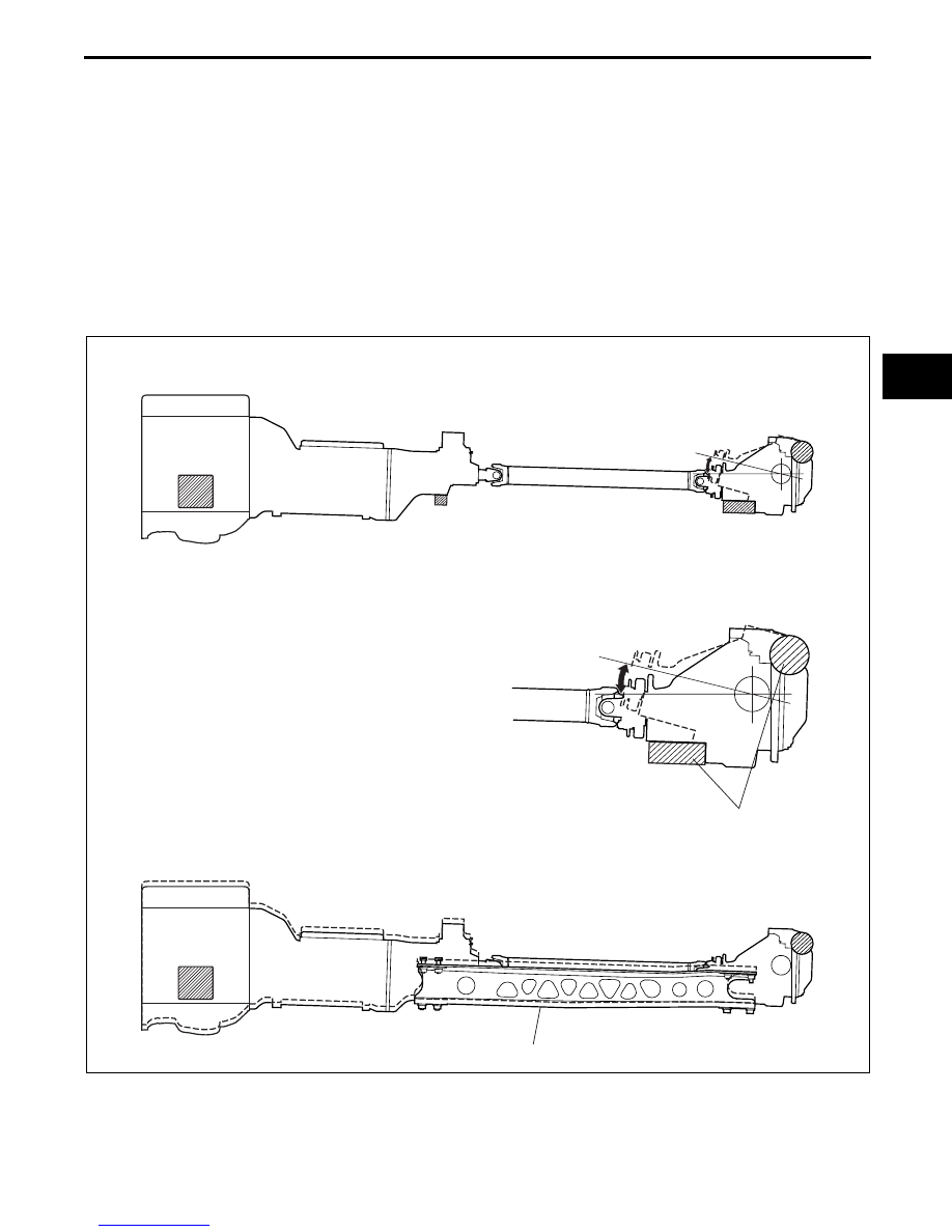
• The power plant frame (PPF) maintains rigidity with a bracket installed between the transmission and the 

differential. Due to this the shift feeling is solid and a feeling of direct drive when starting from a standstill or 
accelerating is created.

Vehicle without PPF

— In order to suppress the transmission of excessive vibration to the vehicle body, rubber mounts are used to 

connect the differential to the frame. When accelerating rapidly, the front part of the differential lifts upward 
which causes a time lag in the actual engine torque being transmitted to the tires and direct drive feeling is lost.

Vehicles with PPF

— With PPF, the transmission and differential are joined in a single unit which, even though the differential is can 

be separated from the body, time lag is lessened due to the near elimination of lift, creating a feeling of direct 
drive. Furthermore, shock and vibration during acceleration and deceleration is greatly reduced.

End Of Sie

RUBBER MOUNT

LIFT

POWER PLANT FRAME (PPF)

WITH PPF

WITHOUT PPF

E5U513ZS5040

MANUAL TRANSMISSION [P66M-D]

05–11B–1

05–11B

05–11B MANUAL TRANSMISSION [P66M-D]

 6-SPEED MT

MANUAL TRANSMISSION OUTLINE

[P66M-D] . . . . . . . . . . . . . . . . . . . . . . . .  05–11B–1

MANUAL TRANSMISSION

CROSS-SECTIONAL VIEW
[P66M-D] . . . . . . . . . . . . . . . . . . . . . . . .  05–11B–1

MANUAL TRANSMISSION POWER

FLOW [P66M-D]  . . . . . . . . . . . . . . . . . .  05–11B–2

SHIFT MECHANISM [P66M-D] . . . . . . . .  05–11B–3

 Shift rod. . . . . . . . . . . . . . . . . . . . . . . .  05–11B–3

TRIPLE SYNCHRONIZER MECHANISM 

STRUCTURE [P66M-D]  . . . . . . . . . . . .  05–11B–4

Features . . . . . . . . . . . . . . . . . . . . . . . .  05–11B–4
Structure  . . . . . . . . . . . . . . . . . . . . . . .  05–11B–4

TRIPLE SYNCHRONIZER MECHANISM 

OPERATION [P66M-D] . . . . . . . . . . . . .  05–11B–5

SHIFT INTERLOCK MECHANISM 

FUNCTION [P66M-D] . . . . . . . . . . . . . . . 05–11B–6

SHIFT INTERLOCK MECHANISM 

OPERATION [P66M-D]. . . . . . . . . . . . . . 05–11B–6

Structure . . . . . . . . . . . . . . . . . . . . . . . . 05–11B–6
Operation  . . . . . . . . . . . . . . . . . . . . . . . 05–11B–6

REVERSE LOCKOUT MECHANISM

FUNCTION [P66M-D] . . . . . . . . . . . . . . . 05–11B–8

REVERSE LOCKOUT MECHANISM 

CONSTRUCTION/OPERATION
[P66M-D]. . . . . . . . . . . . . . . . . . . . . . . . . 05–11B–8

POWER PLANT FRAME (PPF)

FUNCTION [P66M-D] . . . . . . . . . . . . . . . 05–11B–8

End of Toc

MANUAL TRANSMISSION OUTLINE [P66M-D]

E5U051100000N01

• A linked, triple-cone synchronizer mechanism has been adopted for 1st, 2nd, 3rd and 4th gears.

• A guide plate type reverse lockout mechanism has been adopted.

End Of Sie

MANUAL TRANSMISSION CROSS-SECTIONAL VIEW [P66M-D]

E5U051100000N02

End Of Sie

1ST

2ND

3RD

4TH

5TH

6TH

REV

SHIFT PATTERN

MAIN DRIVE GEAR 
SHAFT 

MAINSHAFT

1ST GEAR 

2ND GEAR

3RD GEAR

4TH GEAR

5TH GEAR

6TH GEAR

REVERSE IDLER GEAR

E5U511BS5007

MANUAL TRANSMISSION [P66M-D]

05–11B–2

MANUAL TRANSMISSION POWER FLOW [P66M-D]

E5U051100000N03

End Of Sie

A

A

1ST

2ND

3RD

4TH

5TH

6TH

REVERSE

E5U511BS5008


Content   ..  70  71  72  73   ..