Lifan 620. Manual - part 88


  Index      Lifan     Lifan 620 - service repair manual 2008 year


Search            


Content   ..  86  87  88  89   ..


Lifan 620. Manual - part 88


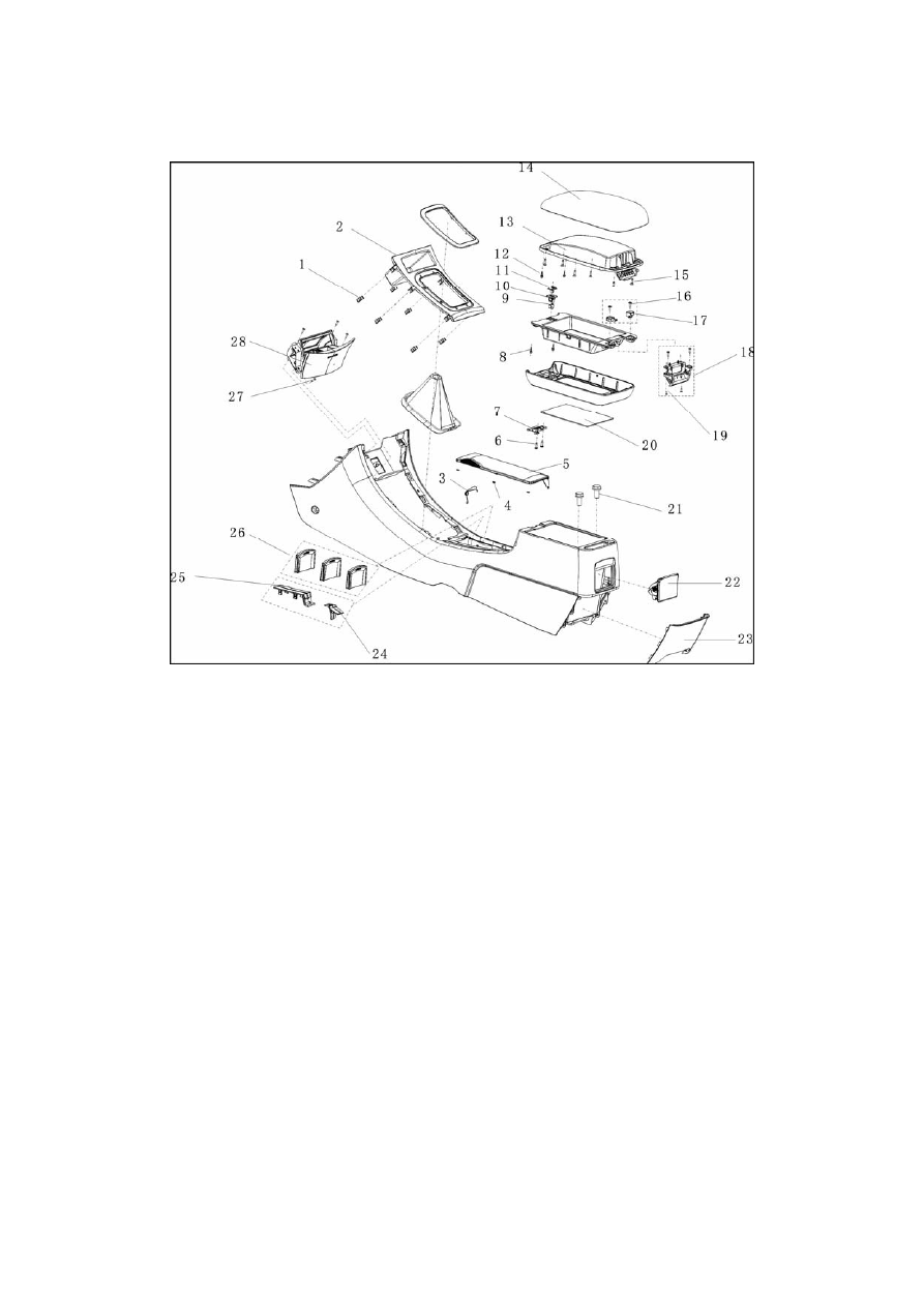
XI. Auxiliary fascia console (Fig. 7-42) 
 

15. Connecting screw of inner and outer panels of upper cover of sundries box cover on auxiliary fascia console 

16. Upper retroflex hinge mounting screw of sundries box on auxiliary fascia console       

17. Upper retroflex hinge mechanism of sundries box on auxiliary fascia console       

18. Lower retroflex hinge mechanism of sundries box on auxiliary fascia console 

19. Mounting screw of lower retroflex hinge mechanism of sundries box on auxiliary fascia console       

20. Inner felt pad of sundries box on auxiliary fascia console                   21. Installing bolt 

22. Small assembly of rear ashtray             23. Rear guard panel of auxiliary fascia console passage       

24. Rubber stopper of handbrake cover board   25. Handbrake cover board    

26. Front cup salver clapboard                27. Installing screw          28. Front ashtray assembly 


353

1. Removal 

1) Remove trim strip of instrument panel and A/C control panel. 

2) Remove the two screws fastening instrument panel and auxiliary fascia console under the A/C 

control panel. 

3) Remove and replace screw 3 (2 screws in left and right) 

4) Remove floor type handbrake cover board. 

5) Open sundries case cover of auxiliary fascia console and remove the two bolts in the bottom.   

6) Remove auxiliary fascia console assembly. 


Fig. 7-43 

1. Cross slot recessed hexangular head self-tapping screw      2. Rubber head bolt     3. Plastic buckle 

4. Cross slot cup head self-tapping screw     5. Front grille     6. Mark     7. Front bumper   

8. Cross slot hexangular head self-tapping screw 


1. Remove front grille 

Remove the mounting buckle of front grille and two rubber head bolts. 

2. Disconnect the 3 jack catches and remove grille with a screwdriver. 

Note: Wrap the screwdriver tip with adhesive tape before use. 

354

3. Remove mudguard of left front wheel. 

(a) Remove 2 screws. 

(b) Remove mudguard of left front wheel. 

Notes:  

It is not necessary to completely remove the mudguard of left front wheel; the bumper can be 

removed in Step 4 if it is partly removed. 

4. Remove mudguard of right front wheel. Notes: the same with Step 2. 

5. Remove the other 2 screws connecting front bumper and engine mudguard. 

15. Install front bumper framework. 

Install front bumper framework with 4 nuts and 4 bolts. 

16. Install left connection bracket of front bumper. 

17. Install right connection bracket of front bumper. 

18. Install front bumper framework. 

19. Install front grille with 2 bolts.                                                                                                     


355

XIII. Rear bumper components (Fig. 7-44) 


6. Remove right rear combination headlamp. Notes: the same with Step 5. 

7. Remove left rear small mudguard 
① Remove 2 screws and left rear small mudguard. 
② Remove BL234 snap button and matching washer Q40208. Notes: Turn the sub-button with a 

cross-tip screwdriver in counter-clockwise direction. 

8. Remove right rear small mudguard. Notes: the same with Step 7. 

9. Remove rear bumper 
① Remove the 2 self-tapping screws in the left side of rear bumper with Phillips screwdriver.   
② Remove the 2 self-tapping screws in the right side of rear bumper with Phillips screwdriver. 

356


Content   ..  86  87  88  89   ..