LEXUS LC 500H (2019 year). Instruction - part 5


  Index      Lexus     LEXUS LC 500H - instruction 2019 year in english


Search            


Content   ..  3  4  5  6   ..


LEXUS LC 500H (2019 year). Instruction - part 5


74

2-1. Instrument cluster

2-1.Instrument cluster

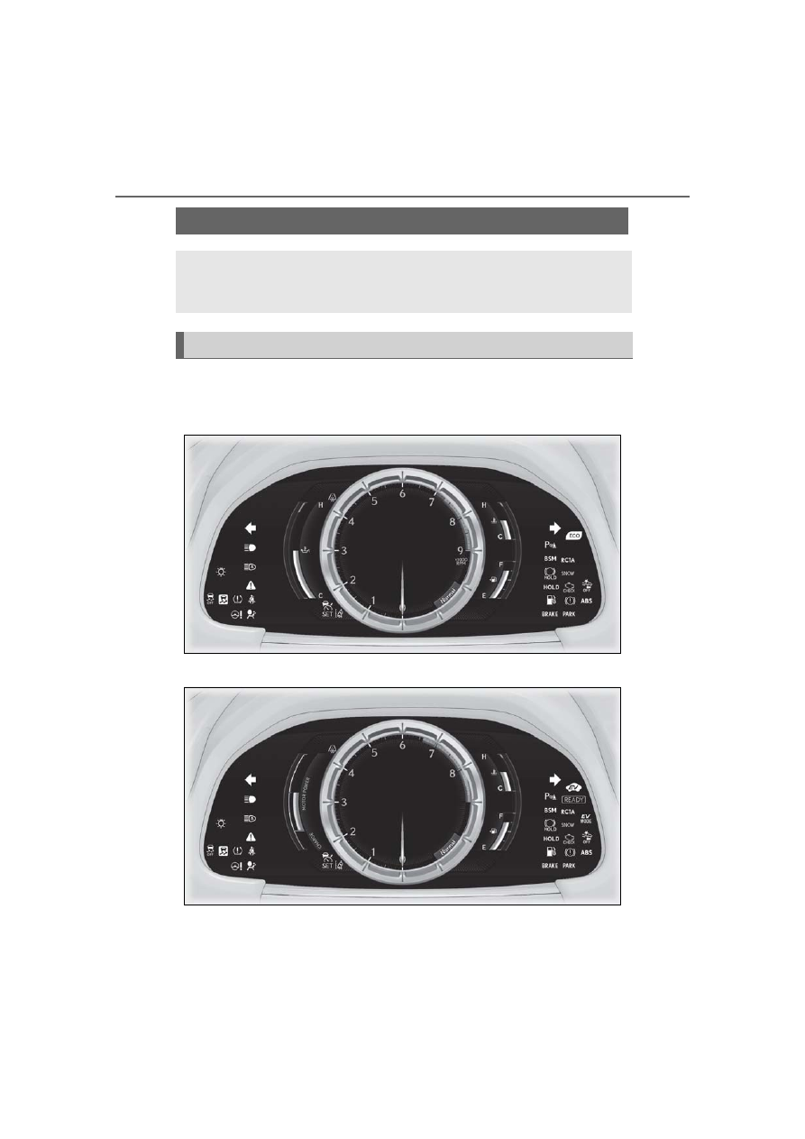
For the purpose of explanation, the following illustrations display all warning lights 
and indicators illuminated.

LC500

LC500h

The units used on the meters and some indicators may differ depending on the target 
region.

Warning lights and indicators

The warning lights and indicators on the instrument cluster, center panel and 
outside rear view mirrors inform the driver of the status of the vehicle’s various 
systems.

Instrument cluster

75

2-1. Instrument cluster

2

Vehi

cle

 status 

inform

ati

on a

nd i

ndic
ators

Warning lights inform the driver of mal-
functions in the indicated vehicle sys-
tems.

*1

: These lights turn on when the engine 

switch <power switch> is turned to 
IGNITION ON mode <ON mode> to 
indicate that a system check is being 
performed. They will turn off after the 
engine <hybrid system> is started, or 

Warning lights

(U.S.A.)

Brake system warning light

*1


(

P.335)

(red)

(Canada)

Brake system warning light

*1


(

P.335)

Charging system warning 
light

*2

 (

P.335)

Low engine oil pressure 
warning light

*2

 (

P.335)

(U.S.A.)

Malfunction indicator lamp

*1


(

P.336)

(Canada)

Malfunction indicator lamp

*1


(

P.336)

SRS warning light

*1


(

P.336)

(U.S.A.)

ABS warning light

*1


(

P.336)

(Canada)

ABS warning light

*1


(

P.336)

(red)

Electric power steering sys-
tem warning light

*1

 (

P.336)

(yellow)

Electric power steering sys-
tem warning light

*1

 (

P.336)

PCS warning light

*1, 3


(

P.337)

(orange)

LKA indicator

*2

 (

P.337)

Slip indicator

*1

 (

P.337)

Brake Override System 
warning light 
(

P.338)/Drive-Start Con-

trol warning light

*2

 (

P.338)

Brake hold operated indica-
tor

*1, 3

 (

P.338)

(U.S.A.)

Parking brake indicator

*3


(

P.338)

(Canada)

Parking brake indicator

*3


(

P.338)

(yellow)

Brake system warning light

*1


(

P.339)

Low fuel level warning light 
(

P.339)

Driver’s and front passen-
ger’s seat belt reminder light 
(

P.339)

Rear passengers’ seat belt 
reminder lights

*4

 (

P.340)

Master warning light

*1


(

P.340)

Tire pressure warning light

*1, 3


(

P.340)

High coolant temperature 
warning light

*2

 (

P.340)

(if equipped)

Hybrid system overheat 
warning light

*2

(

P.341)

76

2-1. Instrument cluster

after a few seconds. There may be a 
malfunction in a system if a light does 
not come on, or turn off. Have the vehi-
cle inspected by your Lexus dealer.

*2

: This light illuminates on the multi-infor-

mation display.

*3

: The light flashes to indicate a malfunc-

tion.

*4

: This light illuminates on the center 

panel.

The indicators inform the driver of the 
operating state of the vehicle’s various 
systems.

Operation indicators

WARNING

If a safety system warning light does 

not come on

Should a safety system light such as the 

ABS and SRS warning light not come on 

when you start the engine <hybrid sys-

tem>, this could mean that these systems 

are not available to help protect you in an 

accident, which could result in death or 

serious injury. Have the vehicle inspected 

by your Lexus dealer immediately if this 

occurs.

Indicators

Turn signal indicator (

P.167)

(U.S.A.)

Headlight indicator (

P.173)

(Canada)

Tail light indicator (

P.173)

Headlight high beam indica-
tor (

P.175)

Automatic High Beam indica-
tor

*1

 (

P.176)

Cruise control indicator

*2


(

P.203)

Dynamic radar cruise control 
indicator

*2

 (

P.203)

Cruise control “SET” indica-
tor

*2

 (

P.203)

(white)

LKA indicator

*2

 (

P.196)

(green)

LKA indicator

*2

 (

P.196)

(orange)

LKA indicator

*2, 3

 (

P.196)

(if equipped)

Intuitive parking assist indica-
tor (

P.214)

Slip indicator

*1, 3

 (

P.232)

VSC OFF indicator

*1


(

P.233)

PCS warning light

*1, 4


(

P.191)

BSM (Blind Spot Monitor) 
outside rear view mirror indi-
cators

*5, 6

 (

P.220)

BSM (Blind Spot Monitor) 
indicator (

P.220)

RCTA (Rear Cross Traffic 
Alert) indicator (

P.220)

Brake hold standby indica-
tor

*1

 (

P.171)

Brake hold operated indica-
tor

*1

 (

P.171)

Security indicator

*7

 (

P.69, 

71)
Smart access system with 
push-button start indicator

*2


(

P.146, 149)

77

2-1. Instrument cluster

2

Vehi

cle

 status 

inform

ati

on a

nd i

ndic
ators

*1

: These lights turn on when the engine 

switch <power switch> is turned to 
IGNITION ON mode <ON mode> to 
indicate that a system check is being 
performed. They will turn off after the 
engine <hybrid system> is started, or 
after a few seconds. There may be a 
malfunction in a system if a light does 
not come on, or turn off. Have the vehi-
cle inspected by your Lexus dealer.

*2

: This light illuminates on the multi-infor-

mation display.

*3

: The light flashes to indicate that the sys-

tem is operating.

*4

: The light comes on when the system is 

turned off.

*5

: In order to confirm operation, the BSM 

outside rear view mirror indicators illu-
minate in the following situations: 
When the engine switch <power switch> 
is turned to IGNITION ON mode <ON 
mode> while the BSM main switch is 
turned on. 
When the BSM main switch is turned 
on while the engine switch <power 
switch> is in IGNITION ON mode 
<ON mode>. 
If the system is functioning correctly, the 
BSM outside rear view mirror indica-
tors will turn off after a few seconds. 
If the BSM outside rear view mirror indi-
cators do not illuminate or do not turn 
off, there may be a malfunction in the 
system. 
If this occurs, have the vehicle inspected 
by your Lexus dealer.

(if equipped)

“READY” indicator (

P.149)

Low outside temperature 
indicator

*2, 8

 (

P.80)

(if equipped)

Eco Driving Indicator Light

*1


(

P.78)

(if equipped)

EV indicator (

P.62)

(U.S.A.)

Parking brake indicator 
(

P.168)

(Canada)

Parking brake indicator 
(

P.168)

Snow mode indicator 
(

P.159, 165)

(if equipped)

EV drive mode indicator 
(

P.153)

“Normal” indicator

*2


(

P.213)

“Eco” indicator

*2

 (

P.213)

“Sport S” indicator

*2


(

P.213)

“Sport S+” indicator

*2


(

P.213)

“Comfort” indicator

*2


(

P.213)

“Custom” indicator

*2


(

P.213)

(U.S.A.)

“AIR BAG ON/OFF” 
indicator

*7

 (

P.38)

(Canada)

“AIR BAG ON/OFF” 
indicator

*7

 (

P.38)

78

2-1. Instrument cluster

*6

: This light illuminates on the outside rear 

view mirrors.

*7

: This light illuminates on the center 

panel.

*8

: When the outside temperature is 

approximately 37°F (3°C) or lower, the 
indicator will flash for approximately 10 
seconds, then stay on.

Eco Driving Indicator (LC500)

Eco Driving Indicator Light

During Eco-friendly acceleration (Eco driv-
ing), the Eco Driving Indicator Light will 
turn on. When the acceleration exceeds the 
Zone of Eco driving, or when the vehicle is 
stopped, the light turns off.
Eco Driving Indicator can be enabled on 
the multi-information display. (

P.84)

Eco Driving Indicator Zone Display

Suggests the Zone of Eco driving with cur-
rent Eco driving ratio based on accelera-
tion.

Eco driving ratio based on acceleration

The part that exceeds the Zone of Eco driv-
ing illuminates in white.

Zone of Eco driving

Eco Driving Indicator will not operate 

under the following conditions:

The shift position is in any position other 

than D.

A paddle shift switch is operated.

Eco Driving Indicator Light:

Neither normal mode nor Eco drive 

mode is selected.

Eco Driving Indicator Zone Display:

Eco drive mode is not selected.

The vehicle speed is approximately 80 

mph (130 km/h) or higher.

Hybrid System Indicator (LC500h)

Charge area

Shows regeneration

*

 status. Regenerated 

energy will be used to charge the hybrid 
battery (traction battery).

Hybrid Eco area

Shows that gasoline engine power is not 
being used very often.
The gasoline engine will automatically stop 
and restart under various conditions.

Eco area

Shows that the vehicle is being driven in an 
Eco-friendly manner.
By keeping the indicator needle within Eco 
area, more Eco-friendly driving can be 

A

B

C

D

A

B

C

79

2-1. Instrument cluster

2

Vehi

cle

 status 

inform

ati

on a

nd i

ndic
ators

achieved.

Power area

Shows that an Eco-friendly driving range is 
being exceeded (during full power driving 
etc.)
In the following situation, the Hybrid System 
Indicator does not operate.

*

: When used in this manual, “regeneration” 

refers to the conversion of energy cre-
ated by the movement of the vehicle into 
electrical energy.

The shift position is in other than D or M.

The driving mode is other than Eco 

mode.

Motor power display (LC500h)

Motor power area

Shows that the power of the motor assists 
the engine.

Charge area

Shows regeneration

*

 status. Regenerated 

energy will be used to charge the hybrid 
battery (traction battery).

*

: When used in this manual, “regeneration” 

refers to the conversion of energy cre-
ated by the movement of the vehicle into 
electrical energy.

D

A

B

80

2-1. Instrument cluster

LC500

LC500h

The units used on the meters may differ depending on the target region.

Engine oil temperature gauge/Eco Driving Indicator (LC500)

Displays the engine oil temperature or Eco Driving Indicator (

P.78)

Outside temperature

Gauges and meters

When the main meter is in the side position, some of the meter displays and the 
gauge layout will be changed.

Meter display

A

B

81

2-1. Instrument cluster

2

Vehi

cle

 status 

inform

ati

on a

nd i

ndic
ators

Displays the outside temperature within the range of -40°F (-40°C) to 122°F (50°C) 
Low outside temperature indicator comes on when the ambient temperature is 37°F (3°C) 
or lower

Tachometer

Displays the engine speed in revolutions per minute

Speedometer

Shift position/shift range/gear position (

P.155, 161)

Shift position indicator (

P.157, 163)

Clock

Time displayed is linked to the analog clock on the instrument panel. (

P.264)

Engine coolant temperature gauge

Displays the engine coolant temperature 
If the engine coolant temperature gauge indicator enters the red zone, a buzzer sounds 
and the high coolant temperature warning light comes on

Odometer and trip meter display

Odometer: 
Displays the total distance the vehicle has been driven
Trip meter: 
Displays the distance the vehicle has been driven since the meter was last reset 
Trip meters “A” and “B” can be used to record and display different distances independently

Fuel gauge

Displays the quantity of fuel remaining in the tank

Multi-information display

Presents the driver with a variety of vehicle data (

P.84)

Displays warning messages in case of a malfunction (

P.344)

Motor power display/Hybrid System Indicator (LC500h)

Displays the motor power display (

P.79) or Hybrid System Indicator (P.78)

Rev indicator

When the engine speed reaches a set 
speed or the red zone, a ring-shaped 
indicator will be displayed on the 
tachometer.
The indicators will be displayed in 
amber (

) when the engine speed 

reaches a set speed, and in red (

when the engine speed reaches the 
red zone. This setting can be enabled 
on the multi-information display. 
(

P.89)

C

D

E
F

G

H

I

J

K

L

A

B

82

2-1. Instrument cluster

Rev peak

When the engine speed reaches or 
exceeds the following, an afterimage of 
the tachometer will be displayed at the 
highest engine speed for approxi-
mately 1 second.
LC500: 3600 r/min
LC500h: 4000 r/min

The meters and display illuminate when

The engine switch <power switch> is in 

IGNITION ON mode <ON mode>.

Variable red zone (LC500)

To help protect the engine, the engine 

speed is controlled by starting the red zone 

of the tachometer at different engine 

speeds ranging from 3700 rpm to 7300 

rpm depending on the engine coolant tem-

perature. 

Before driving under extremely high load 

conditions, make sure to sufficiently warm 

up the engine.

Instrument panel brightness adjustment

The brightness of the instrument panel 

lights is automatically adjusted based on the 

light sensor detecting how bright the sur-

roundings are.

Outside temperature display

In the following situations, the correct 

outside temperature may not be dis-

played, or the display may take longer 

than normal to change.

• When stopped, or driving at low speeds 

(less than 12 mph [20 km/h])

• When the outside temperature has 

changed suddenly (at the entrance/exit of 

a garage, tunnel, etc.)

When “- -” or “E” is displayed, the system 

may be malfunctioning. 

Take your vehicle to your Lexus dealer.

Speed unit setting for the speedometer

When the speed unit has been changed 

from the default setting, the vehicle speed in 

the default unit is also displayed in the 

meter.

Pop-up display

In some situations, such as when a switch 

operation is performed, a pop-up display 

will be temporarily displayed on the 

multi-information display.

Some pop-up displays can be set on/off. 

(

P.88)

83

2-1. Instrument cluster

2

Vehi

cle

 status 

inform

ati

on a

nd i

ndic
ators

Liquid crystal display

Small spots or light spots may appear on the 

display. This phenomenon is characteristic 

of liquid crystal displays, and there is no 

problem continuing to use the display.

Customization

The meter display can be customized on 

the multi-information display. (

P.391)

The odometer and trip meter displays 
can be switched. When the trip meter 
is displayed, pressing and holding the 
button will reset the trip meter.

The brightness of the instrument panel 
lights can be adjusted.

1

Darker

2

Brighter

Instrument panel brightness adjustment

The instrument panel brightness levels 

when the tail lights are on and off can be 

adjusted individually. However, when the 

surroundings are bright (daytime, etc.), 

turning on the tail lights will not change the 

instrument panel brightness.

The display can be switched between 
the center and side positions.

NOTICE

To prevent damage to the engine and 

its components

Do not let the indicator of the tachom-

eter enter the red zone, as it rep-

resents the engine speed range which 

exceeds the maximum safe engine 

speed.

In the following situations, the engine 

may be overheating. In this case, 

immediately stop the vehicle in a safe 

place, and check the engine after it has 

cooled completely. (

P.364, 366)

• The engine coolant temperature 

gauge is in the red zone (H).

• LC500: The engine oil temperature 

gauge is in the red zone (H).

Changing between the odome-
ter and trip meter

Changing the Instrument panel 
light brightness

Changing the display

84

2-1. Instrument cluster

Display

When the main meter is in the cen-
ter position

Displays various drive information on 
the main meter.
Some of the contents which are dis-
played when the main meter is in the 
side position cannot be displayed. 
(

P.85)

When the main meter is in the side 
position

Selecting a menu icon displays a vari-
ety of vehicle data or allows vehicle 
settings to be customized.

Menu icons

Multi-information display

Display and menu icons

Drive information

Navigation system-linked dis-
play

Audio system-linked display

Driving assist system informa-
tion

85

2-1. Instrument cluster

2

Vehi

cle

 status 

inform

ati

on a

nd i

ndic
ators

Opening image display

When the engine switch <power switch> is 

in ACCESSORY mode or IGNITION ON 

mode <ON mode>, the opening image is 

displayed on the multi-information display. 

While the opening image is being dis-

played, the meter display cannot be 

changed even if the drive mode is changed. 

When the start-up display is finished, the 

meter display for the currently selected 

mode will be displayed.

When disconnecting and reconnecting 

12-volt battery terminals

Record of the maximum G-forces will be 

reset.

Liquid crystal display

P.83

The multi-information display is oper-
ated using the meter control switches.

/

: Switch menu

/

: Change displayed con-

tent, scroll up/down the screen and 
move the cursor up/down

Press: Enter/Set
Press and hold: Reset

Return to the previous screen and 
move the main meter

Content of drive information

Select to display various drive data.

Warning message display

Settings display

WARNING

Caution for use while driving

When operating the multi-information 

display while driving, pay extra atten-

tion to the safety of the area around the 

vehicle.

Do not look continuously at the multi-

information display while driving as 

you may fail to see pedestrians, objects 

on the road, etc. ahead of the vehicle.

The information display at low tem-

peratures

Allow the interior of the vehicle to warm 

up before using the liquid crystal infor-

mation display. At extremely low tem-

peratures, the information display 

monitor may respond slowly, and display 

changes may be delayed. 

For example, there is a lag between the 

driver’s shifting and the new gear number 

appearing on the display. This lag could 

cause the driver to downshift again, 

causing rapid and excessive engine brak-

ing and possibly an accident resulting in 

death or injury.

Changing the meter display

Drive information

A

B

C

86

2-1. Instrument cluster

Up to 2 of the following items can be 
selected.
Items displayed can be switched by 
pressing 

 or 

 of the meter con-

trol switches to select 

 and pressing 

 or 

.

 Current fuel consumption

*1

Displays the current rate of fuel consump-
tion

 Average fuel economy (after 

reset

*2

/after start/after refuel)

*1

Displays the average fuel consumption 
since the function was reset, the engine 
<hybrid system> was started, and the vehi-
cle was refueled, respectively
Use the displayed average fuel consump-
tion as a reference.

 Average speed (after reset

*2

/after 

start)

*1

Displays the average vehicle speed since 
the function was reset and the engine 
<hybrid system> was started, respectively

 Elapsed time (after reset

*2

/after 

start)

*1

Displays the elapsed time since the func-
tion was reset and the engine <hybrid sys-
tem> was started, respectively

 Distance (range/after start)

*1

Displays the estimated maximum distance 
that can be driven with the quantity of fuel 
remaining and the distance driven after the 
engine <hybrid system> was started 
respectively.
• This distance is computed based on your 

average fuel consumption. As a result, 
the actual distance that can be driven 

may differ from that displayed.

• When only a small amount of fuel is 

added to the tank, the display may not be 
updated. 
When refueling, turn the engine switch 
<power switch> off. If the vehicle is refu-
eled without turning the engine switch 
<power switch> off, the display may not 
be updated.

*1

: Displayed when the item is set in “Drive 

Info 1” and “Drive Info 2”.

*2

: The function can be reset by pressing 

“OK” of the meter control switches for 
longer than 1 second when the item to 
reset is displayed. 
If there is more than one item that can 
be reset, the item selection screen will 
appear.

Eco Driving Indicator/engine oil 
temperature gauge (LC500)

P.78, 80

Hybrid System Indicator/motor 
power display (LC500h)

P.78

Energy monitor (LC500h)

P.95

Tire pressure

P.303

Gear positions

Displays the current shift range or gear 
position when the shift position is in D 
or M.

Units

The units of measure used can be 
changed while driving.

Unlike the units setting performed on the 
settings display, the units setting per-
formed on the drive information menu can 

87

2-1. Instrument cluster

2

Vehi

cle

 status 

inform

ati

on a

nd i

ndic
ators

be changed while driving.

G-force

Displays lateral G-forces on the vehi-
cle
 Reading the display

• Normal display
Displays the following on the multi-infor-
mation display

Acceleration G-force on the vehicle

Current G-force value (analyzed value 
of front/rear and left/right G-forces)

• Advanced display
Displays the following on the main meter 
and multi-information display
Multi-information display:

Acceleration G-force on the vehicle

Record of the maximum G-forces

Value of the maximum G-force since 
display reset (analyzed value of 

front/rear and left/right G-forces)

This display is intended for use as a guide-
line. Depending on factors such as the road 
surface condition, temperature and vehicle 
speed, the display may not show the actual 
condition of the vehicle.
Main meter:

G-force direction

Current G-force value (analyzed value 
of front/rear and left/right G-forces)

This display is intended for use as a guide-
line. Depending on factors such as the road 
surface condition, temperature and vehicle 
speed, the display may not show the actual 
condition of the vehicle.

 Switching the display

To switch to advanced display, press “OK”.
To return to normal display, press “OK”.

 Resetting the record of maximum 

G-forces

With the record of maximum G-forces dis-
played, press and hold “OK” to reset the 
display.

 Peak hold function (advanced dis-

play only)

If lateral G-forces of 0.5 G or greater are 
generated, the G-force value displayed on 
the main meter will turn yellow and be held 
for 3 seconds.

A

B

A

B

C

A

B

88

2-1. Instrument cluster

Rear wing position (if equipped)

Displays the raised/retracted state of 
the active rear wing

LKA (Lane-Keeping Assist) vehicle 
sway warning

P.197

Display off

A blank screen is displayed

Select to display the following naviga-
tion system-linked information.
 Route guidance
 Compass display

Select to enable selection of an audio 
source or track on the meter using the 
meter control switches.

Select to display the dynamic radar 
cruise control with full-speed 
range/LKA (Lane-Keeping Assist) 
information, when the system is used.

Select to display warning messages 
and measures to be taken if a malfunc-
tion is detected. (

P.344)

Select to change the meter display set-
tings.

Language

Select to change the language on the 
display.

Units

Select to change the unit of measure 
for fuel consumption.

Eco Driving Indicator Light 
(LC500)

Select to activate/deactivate the Eco 
Driving Indicator Light.

EV indicator (LC500h)

Select to activate/deactivate the EV 
indicator.

Drive information 1/Drive infor-
mation 2

Select to select up to 2 items that will 
be displayed on the “Drive Info 1” 
screen and “Drive Info 2” screen 
respectively. (

P.85)

Pop-up display

Select to set the following pop-up dis-
plays, which may appear in some situa-
tions, on/off.
• Route guidance display of the navi-

gation system-linked system

• Making call display of the hands-

free phone system

Navigation system-linked dis-
play

Audio system-linked display

Driving assist system information

Warning message display

Settings display

89

2-1. Instrument cluster

2

Vehi

cle

 status 

inform

ati

on a

nd i

ndic
ators

• Audio system operation display
• Voice recognition display
• Instrument panel brightness adjust-

ment display

Ring position memory

Select to change the meter ring posi-
tion when the engine <hybrid system> is 
started.
The position before the engine <hybrid 
system> is stopped or the center posi-
tion can be selected.

Accent color

Select to change the accent color on 
the screen, such as the cursor color.

Rev indicator

Select to set the rev indicator on/off.
When set to on, proceed to select the 
engine speed at which the rev indicator 
will be displayed.

Rev peak

Select to set the rev peak on/off.

Clock

Select to switch between 12-hour dis-
play and 24-hour display.

Initialization

Select to reset the meter display set-
tings.

Suspension of the settings display

In the following situations, operation of the 

settings display will be temporarily sus-

pended.

When a warning message appears on the 

multi-information display

When the vehicle begins to move

Customization

The settings can be changed on 

 of the 

multi-information display.

Settings of the driving assist systems 

(

P.391)

Vehicle settings (

P.91, 283, 306, 308, 

391)

Displays suggestions to the driver in 
the following situations. For some sug-
gestions, a response to a displayed 
suggestion can be selected. To select a 
response, use the meter control 
switches.

Suggestion to turn on the head-
lights

If the headlight switch is in other than 

 or 

 position, and the vehicle 

speed is 3 mph (5 km/h) or higher for 
a certain amount of time when the sur-

WARNING

Cautions during setting up the dis-

play

As the engine <hybrid system> needs to 

be running <operating> during setting up 

the display, ensure that the vehicle is 

parked in a place with adequate ventila-

tion. In a closed area such as a garage, 

exhaust gases including harmful carbon 

monoxide (CO) may collect and enter 

the vehicle. This may lead to death or a 

serious health hazard.

NOTICE

While setting up the display

To prevent 12-volt battery discharge, 

ensure that the engine is running <hybrid 

system is operating> while setting up the 

display features.

Suggestion function


Content   ..  3  4  5  6   ..