Lexus SC300 / Lexus SC400. Manual - part 697
DESCRIPTION
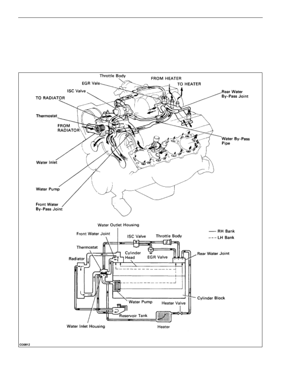
This engine utilizes a pressurized forced circulation cooling system which includes a hermostat equipped
with a by–pass valve mounted on the inlet side.
The cooling system is composed of the water jacket (inside the cylinder block and cylinderhead), radiator,
water pump, thermostat, cooling fan, hoses and other components.
OPERATION
CO–2
–
COOLIING SYSTEM
Description