Range Rover Sport. Manual - part 97
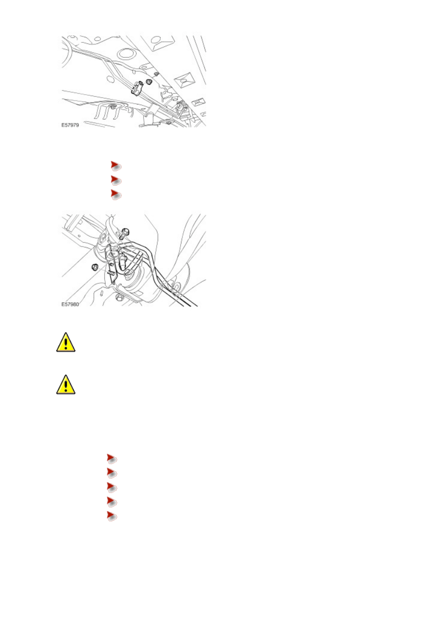
Remove the nut.
Remove the bolt.
Remove the bracket.
9
.
CAUTION: Before disconnecting or removing the components, ensure the area around the joint
faces and connections are clean. Plug open connections to prevent contamination.
CAUTION: Make sure the actuator fluid lines are not damaged or kinked during removal or
installation.
NOTE:
Some fluid spillage is inevitable during this operation.
Disconnect the fluid lines from the actuator.
Position container to collect fluid loss.
Remove the 2 bolts.
Remove and discard the O-ring seals.
Remove and discard the plastic spacer washers.
Install blanking caps to the exposed ports.