Range Rover Sport. Manual - part 90


  Index      Land Rover     Range Rover Sport - service repair manual 2005-2009 year


Search            


Content   ..  88  89  90  91   ..


Range Rover Sport. Manual - part 90


  CAUTION: Before disconnecting or removing the components, ensure the area around the joint

faces and connections are clean. Plug open connections to prevent contamination.

  CAUTION: Make sure the actuator fluid lines are not clamped or kinked. Failure to follow this

instruction will result in damage to the vehicle.

NOTE: 


Some fluid spillage is inevitable during this operation.

NOTE: 


Note the fitted position of the washers.

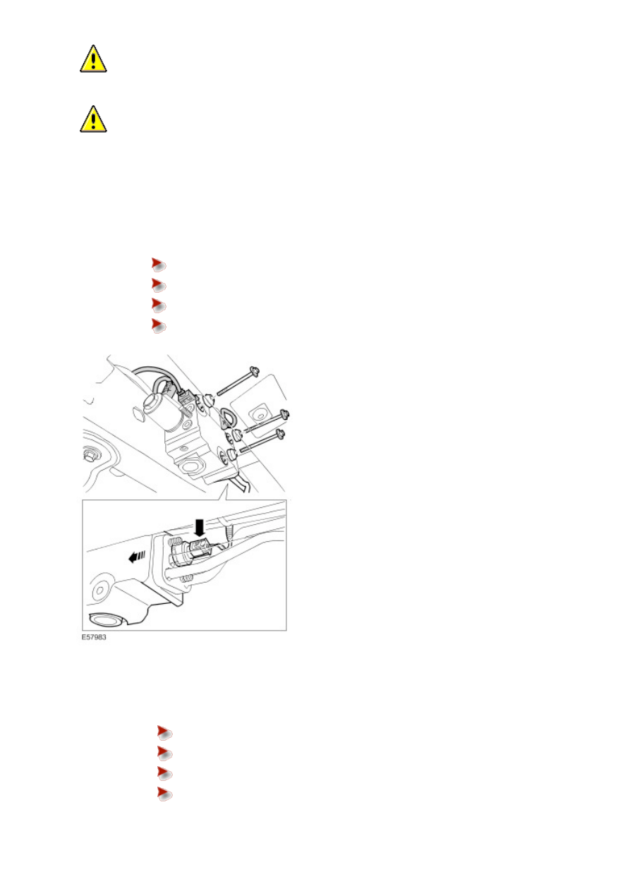
Remove the valve block.


Disconnect the 4 electrical connectors.


Remove the 3 bolts.


Collect the 4 washers.


Disconnect the front actuator pipes from the valve block.

Installation

1 . Check the valve block O-rings seals and plastic spacer washers are correctly installed.


A: Backing rings (white)


B: Outer clamping ring


C: O-ring seals


D: Outer backing ring (Black)

NOTE: 


Make sure there are two washers installed between the integrated body frame and the valve block lower
retaining bolt.

Install the valve block.


Remove the blanking caps from the ports.


Connect the front actuator pipes to the valve block.


Install 2 new nuts and tighten to 22 Nm (16 lb.ft).


Install the 3 valve block retaining bolts, and tighten to 22 Nm (16 lb.ft).


Connect the electrical connectors.

3 . Connect the rear actuator pipes to the valve block.


Remove the blanking caps from the ports.


Install a new nut and tighten to 22 Nm (16 lb.ft).


Remove the container.

4 . Secure the valve block to rear stabilizer bar actuator pipe assembly mounting.


Install the bracket.


Install the nut and bolt and tighten to 9 Nm (7 lb.ft).


Tighten the nut to 9 Nm (7 lb.ft)

6 . Using T4, bleed the Dynamic Response system.

Valve Block Filter (60.60.21) 

Removal

  CAUTION: Dynamic Response system components are manufactured to very precise tolerances and fine

clearances. It is therefore essential that absolute cleanliness is observed when working with these components.
Always install blanking plugs to any open orifices or lines. Failure to follow this instruction may result in foreign
matter ingress to the Dynamic Response system.

NOTE: 


This procedure does not require the Dynamic Response system to be bled.

1
.

  WARNING: Do not work on or under a vehicle supported only by a jack. Always support the vehicle

on safety stands.

Raise and support the vehicle.

2
.

  CAUTION: Before disconnecting or removing the components, ensure the area around the joint

faces and connections are clean. Plug open connections to prevent contamination.

Remove and discard the valve block filter.


Position container to collect fluid loss.


Remove the access plug.


Remove and discard the access plug O-ring seal.


Using a suitable M6 bolt, release the filter from the valve block.

Installation

1 . Install the new valve block filter.


Clean the component mating faces.


Install a new access plug O-ring seal.


Tighten the access plug to 62 Nm (46 lb.ft).


Remove the container.


Content   ..  88  89  90  91   ..