Range Rover Sport. Manual - part 37


  Index      Land Rover     Range Rover Sport - service repair manual 2005-2009 year


Search            


Content   ..  35  36  37  38   ..


Range Rover Sport. Manual - part 37


pressure and the pressure for the front or rear wheel locations must be adjusted accordingly if the wheel is to be
used under conditions other than with the vehicle loaded to maximum gross vehicle weight.

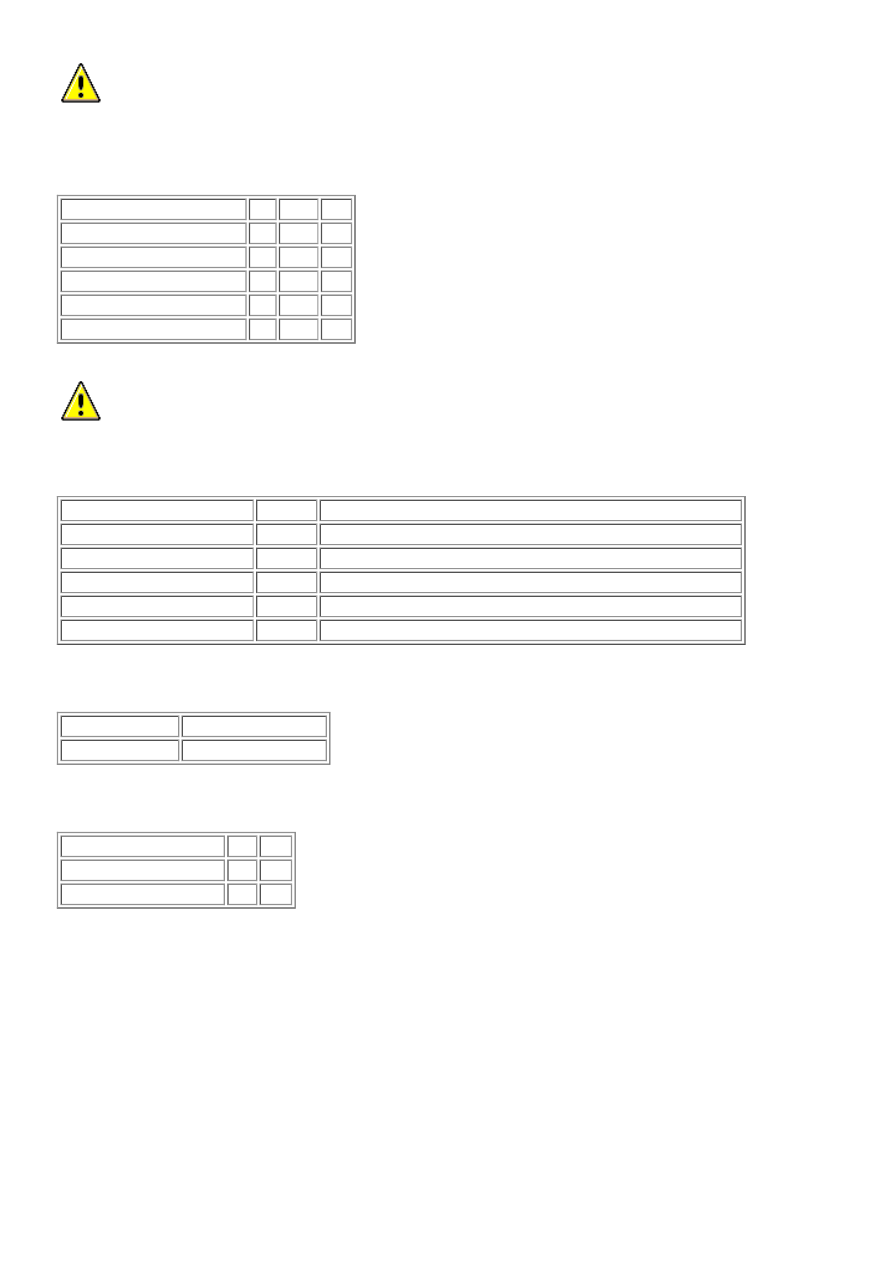
Tire Pressures - NAS Vehicles 

Loading condition

bar lb/in² kPa

All conditions:


Front

2.6 38

260

Rear

2.9 42

290

Reduced size spare wheel

4.2 60

420

* Standard size spare wheel 2.9 42

290

  CAUTION: * The standard size spare wheel tire should always be inflated to the highest loading condition

pressure which must be adjusted accordingly if the wheel is to be installed to the front wheel locations.

General Specification 

Item

Make

Location

Tire low pressure sensor

Siemens On inside of wheel rim

Tire pressure sensor initiator:  


Front

Siemens Attached to the fender splash shield adjacent to the front bumper

Rear

Siemens Attached to the fender splash shield adjacent to the rear bumper

Module

Siemens Attached to the roof behind the roof opening panel.

Recommended Lubricant 

Application

Land Rover Part No.

Wheel hub spigot RYL 105020

Torque Specifications 

Description

Nm lb-ft

* Road wheel nuts

140 103

Tire low pressure sensor 6

4

* Wheel nuts must be tightened by diagonal selection

Wheels and Tires 

GENERAL

A number of alloy wheel and tire size combinations are available. A Tire Pressure Monitoring System (TPMS) is also
available. This system monitors the pressure in each tire and informs the driver if the pressure is outside predetermined
thresholds.

WHEELS

Item Part Number

Description

A


7JX17

B


8JX18 - Style 2

C


8JX18 - Style 3

D


8JX19

E


9JX19

F


9½JX20

G


5½JX19 - Space saver

There are a number of different alloy wheel sizes and styles as shown in the above illustration.

The spare wheel fitted to most vehicles is a steel space saver wheel. The wheel size is 5½J X 19 and uses a T175/80R19
tire. The space saver wheel is a standard fitment for all markets except Gulf states. An 8J X 19 alloy, black painted spare is
offered as an optional fitment. The steel space saver and the alloy spare wheel are subject to a maximum 50 mph (80 km/h)
speed limit.

TIRES

Tires are available in a number of sizes and tread patterns dependent on the vehicle usage. Tire sizes are as follows:

The following tires are available; All Season (AS), All Terrain (AT) and All Terrain - Sport (AT-S).

NOTE: 


Tires should be inflated to the recommended pressures (as given in the owners handbook) only when the tires are
cold (ambient temperature). If the tires have been subjected to use or exposed to direct sunlight, move the vehicle
into a shaded position and allow the tires to cool before checking and/or adjusting the pressures.

Tire Changing

Care must be taken when removing and refitting tires to ensure that the tire pressure sensor is not damaged.

Item Part Number

Description

1


Tire valve and pressure sensor

2


Tire fitting/removal tool initial start position

3


High tire and bead tension area

4


Low tire and bead tension area

When removing the tire, the bead breaker must not be used within 90 degrees of the tire valve in each direction.

When using the tire removal machine, the fitting arm start position must be positioned as shown in the tire changing
illustration. The wheel can then be rotated through 180 degrees in a counterclockwise direction. This will relieve the high
tension from the tire bead allowing the remaining 180 degrees of the tire to be manually pulled from the rim.

When refitting the tire, position the fitting arm as shown. Rotate the tire and take care that the bead on the low tension side
of the tire does not damage the sensor.

Vehicles supplied to the North American markets must comply with the legislation of the Transport Recall Enhancement,
Accountability and Documentation (TREAD) act. Part of the requirement of the TREAD act is for the vehicle to display a
label, positioned on the driver's side B-pillar, which defines the recommended tire inflation pressure, load limits and
maximum load of passengers and luggage the vehicle can safely carry. This label is specific to each individual vehicle and
is installed on the production line.

This label must not be removed from the vehicle. The label information will only define the specification of the vehicle as it
came off the production line. It will not include dealer or owner fitted accessory wheels and tires of differing size from the
original fitment.

If the label is damaged or removed for body repair, it must be replaced with a new label specific to that vehicle. A new label
is requested from Land Rover parts and will be printed specifically for the supplied VIN of the vehicle.

TIRE PRESSURE MONITORING SYSTEM (TPMS)

Tire Pressure Monitoring System - Component Location


Content   ..  35  36  37  38   ..