Range Rover Sport. Manual - part 24


  Index      Land Rover     Range Rover Sport - service repair manual 2005-2009 year


Search            


Content   ..  22  23  24  25   ..


Range Rover Sport. Manual - part 24


Rear Suspension 

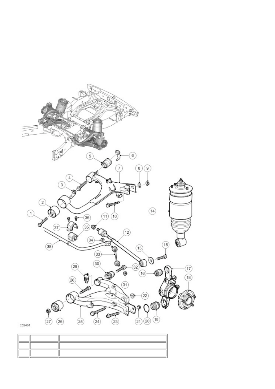
Rear Suspension Component Location

NOTE: 


Without Dynamic Response version shown

Item Part Number

Description

1


Bolt (Upper arm forward bush)

2


Bush - Forward (Upper arm)


Caged nut (Upper arm forward bush)

4


Bolt (Upper arm rearward bush)

5


Bush - Rearward (Upper arm)

6


Caged nut (Upper arm rearward bush)

7


Upper arm

8


Eccentric washer (Wheel knuckle upper ball joint)

9


Nut (Wheel knuckle upper ball joint)

10


Bolt (Wheel knuckle upper ball joint)

11


Special nut (Adjustable transverse toe link)

12


Adjustable transverse toe link

13


Washer (Adjustable transverse toe link)

14


Damper module assembly

15


Bolt (Adjustable transverse toe link)

16


Ball joint (Wheel knuckle upper)

17


Wheel knuckle and bearing assembly

18


Wheel hub

19


Ball joint (Wheel knuckle lower)

20


Circlip (Wheel knuckle lower ball joint)

21


Self-locking nut (Wheel knuckle lower ball joint)

22


Self-locking nut (Damper assembly lower attachment)

23


Bolt (Wheel knuckle lower ball joint)

24


Bolt (Damper assembly lower attachment)

25


Lower arm

26


Bush - Forward (Lower arm)

27


Self-locking nut (Lower arm forward bush)

28


Bolt (Lower arm forward bush)

29


Nut and retainer (Lower arm rearward bush)

30


Bush - Rearward (Lower arm)

31


Self-locking nut (Stabilizer bar link to lower arm)

32


Bolt (Lower arm rearward bush)

33


Stabilizer bar link

34


Self-locking nut (Stabilizer bar link to stabilizer bar)

35


Stabilizer bar bush

36


Bolt (Stabilizer bar bracket)

37


Stabilizer bar bracket

38


Stabilizer bar

GENERAL

The independent rear suspension offers a reduction in unsprung weight over the beam axle design. The rear suspension
comprises an upper arm, a lower arm, a wheel knuckle and wheel hub, two air spring damper modules and a stabilizer bar
and links assembly.

The rear suspension arms have been designed to give maximum ground clearance. The suspension geometery can be
adjusted for camber using a cam bolt and toe and bump steer adjustment can be corrected via an adjustable transverse
link.

AIR SUSPENSION DAMPER MODULE

Description

1

 -

Strap*

2

 -

Upper gaitor*

3

 -

Self-locking nut*

4

 -

Rebound washer*

5

 -

O-ring - Damper rod*

6

 -

Spacer - Damper rod*

7

 -

Air spring*

8

 -

Retaining pin - Air spring sleeve support*

9

 -

Bump washer*

10

 -

Spring aid*

11

 -

O-ring - Air sleeve support (2 off)*

12

 -

Damper rod

13

 -

Damper assembly

14

 -

Strap*

15

 -

Lower gaitor*

16

 -

Strap*

17

 -

Self-locking nut (3 off)

18

 -

Top mount assembly

19

 -

Bush

20

 -

Voss connector

NOTE: 


* Shows service items

The damper module comprises an air spring assembly, top mount and a damper assembly. The damper and air spring are
only serviceable as complete assemblies.

The damper assembly is a mono tube design with an air spring. The lower end of the damper is fitted with a bush and is
attached to the lower arm with a bolt and nut. 

The damper functions by restricting the flow of hydraulic fluid through internal galleries within the damper. The damper rod
moves axially within the damper, its movement limited by the flow of fluid through the galleries, providing damping of
undulations in the terrain. The damper rod is sealed at its exit point from the damper body to maintain the fluid within the unit
and to prevent the ingress of dirt and moisture. The seal also incorporates a wiper to keep the rod clean.

Air Spring

The air spring is similar in design to the air spring used on the front suspension.

The air spring comprises an aluminium restraining cylinder, top mount, spring aid, air sleeve and an inner support sleeve.

The air sleeve is made from a flexible rubber material which allows the sleeve to roll up and down the air spring piston as
the vehicle changes height. The air sleeve is attached to the restraining cylinder and the support sleeve with crimp rings
which provide an air tight seal. The support sleeve contains a seal carrier which has two O-rings sealing the support sleeve
and two O-rings sealing to the damper body. The top of the air sleeve is crimped to the top mount which attaches to a
mounting on the chassis with 3 integral studs and self-locking nuts.

A spring aid is fitted to the damper rod and prevents the top mount contacting the top of the damper during full suspension
compression and assists the suspension tune. The lower end of the air spring is located over the damper body and seats on
a fabricated seat on the damper body. The air sleeve is positively attached to the seat with a retaining pin. The damper rod
is located through a central hole in the top mount. The rod is threaded at its outer end and accepts a self-locking nut which
secures the air spring to the damper rod.

The top mount is an integral part of the air spring. A bump washer is located between the top mount plate and the damper
rod. A self locking nut secures the damper rod to the top mount. The top mount attaches to a housing on the chassis with 3
integral studs and self-locking nuts. The top mount also incorporates a 6 mm Voss air fitting which allows for the attachment
of the air harness.

The air spring is fitted with two gaitors. The upper gaitor is fitted between the top mount and the air spring restraining
cylinder. The lower gaitor is secured to the lower end of the restraining cylinder and the damper body with metal straps. The
gaitors prevent dirt and debris becoming trapped between the air sleeve and the restraining cylinder.

STABILIZER BAR


Content   ..  22  23  24  25   ..