Jeep XJ. Manual - part 800


  Index      Jeep     Jeep XJ - service repair manual 2001 year


Search            


Content   ..  798  799  800  801   ..


Jeep XJ. Manual - part 800


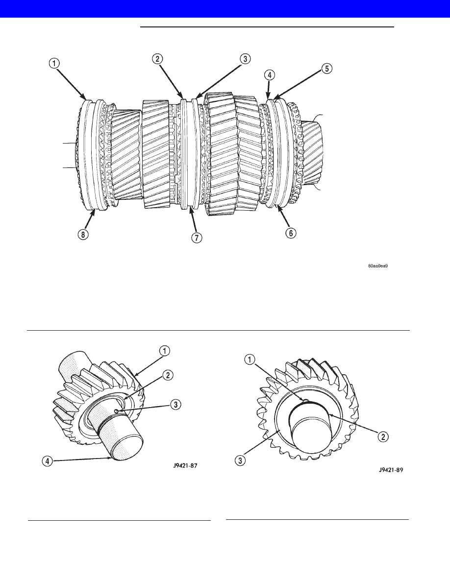
Fig. 76 SYNCHRO SLEEVE LOCATIONS

1 - DOUBLE GROOVE FORWARD
2 - GROOVE FORWARD
3 - FIRST GEAR SIDE MARKING TOWARD FIRST GEAR
4 - TAPER FORWARD
5 - GROOVE FORWARD

6 - 5TH-REV SYNCHRO SLEEVE
7 - 1-2 SYNCHRO SLEEVE
8 - 3-4 SYNCHRO SLEEVE

Fig. 77 IDLER GEAR AND BEARING

1 - IDLER GEAR
2 - BEARING
3 - LOCK BALL
4 - REAR OF SHAFT

Fig. 78 IDLER GEAR REAR THRUST WASHER

1 - LOCK BALL
2 - SNAP RING GROOVE
3 - THRUST WASHER

21s - 22

MANUAL NV 3550

XJ

MANUAL NV 3550 (Continued)

2001 JEEP CHEROKEE

(7) Install lock ball in dimple at front of shaft.

Hold ball in place with petroleum jelly.

(8) Install front thrust washer on shaft and slide

washer up against gear and over lock ball (Fig. 79).

(9) Install wave washer, flat washer and remain-

ing snap ring on idler shaft (Fig. 79). Verify snap
ring is seated.

SHIFT SHAFT AND BUSHINGS/BEARINGS

Inspect shift shaft bushing and bearing for damage

and replace if necessary.

(1) Locate a bolt that will thread into the bushing

without great effort.

(2) Thread the bolt into the bushing, allowing the

bolt to make its own threads in the bushing.

(3) Attach a slide hammer or suitable puller to the

bolt and remove bushing.

(4) Use the short end of Installer 8119 to install

the new bushing.

(5) The bushing is correctly installed if the bush-

ing is flush with the transmission case.

(6) To replace the bearing locate a bolt that will

thread into the bearing without great effort.

(7) Thread the bolt into the bearing as much as

possible.

(8) Attach a slide hammer or suitable puller to the

bolt and remove the bearing.

(9) Use the short end of Installer 8119 to install

the new bearing.

(10) The bearing is correctly installed if the bear-

ing is flush with the transmission case.

DETENT PLUNGER BUSHING

Inspect detent plunger bushings for damage and

replace if necessary.

NOTE: The detent plunger bushings are installed to
a specific depth. The space between the two bush-
ings when correctly installed contain an oil feed
hole. Do not attempt to install the bushings with
anything other than the specified tool or this oil
hole may become restricted.

(1) Using the long end of Installer 8119, drive the

detent bushings through the outer case and into the
shift shaft bore.

(2) Remove the bushings from the shift shaft bore.
(3) Install a new detent plunger bushing on the

long end of Installer 8118.

(4) Start the bushing in the detent plunger bore in

the case.

(5) Drive the bushing into the bore until the tool

contacts the transmission case.

(6) Install a new detent plunger bushing on the

short end of Installer 8118.

(7) Start the bushing in the detent plunger bore in

the case.

(8) Drive the bushing into the bore until the tool

contacts the transmission case.

Fig. 79 IDLER GEAR AND SHAFT ASSEMBLY

1 - REAR OF SHAFT
2 - GEAR
3 - THRUST WASHER AND BALL
4 - WAVE WASHER
5 - FLAT WASHER
6 - FRONT OF SHAFT
7 - SNAP RING
8 - SNAP RING

XJ

MANUAL NV 3550

21s - 23

MANUAL NV 3550 (Continued)

2001 JEEP CHEROKEE

GEARTRAIN ASSEMBLY

(1) Install Adapter 6747-1A on input shaft hub of

Fixture 6747 (Fig. 80).

(2) Install input shaft in fixture tool. Make sure

Adapter 6747-1A is positioned under shaft as shown
(Fig. 81).

(3) Install pilot bearing in input shaft (Fig. 81).

NOTE: The side of the pilot bearing with the small
diameter goes toward the input shaft.

(4) Install fourth gear synchro ring on input shaft

(Fig. 82).

(5) Adjust height of idler gear pedestal on assem-

bly fixture (Fig. 83). Start with a basic height of 18.4
cm (7-1/4 in.). Final adjustment can be made after
gear is positioned on pedestal.

Fig. 80 ASSEMBLY FIXTURE FOR GEARTRAIN

1 - SPECIAL TOOL 6747-2A
2 - SPECIAL TOOL 8115
3 - SPECIAL TOOL 6747-1A
4 - SPECIAL TOOL 6747

Fig. 81 PILOT BEARING AND INPUT SHAFT

1 - PILOT BEARING
2 - INPUT SHAFT

Fig. 82 FOURTH GEAR SYNCHRO

1 - FOURTH GEAR SYNCHRO RING
2 - INPUT SHAFT

Fig. 83 IDLER PEDESTAL BASIC HEIGHT

1 - REVERSE IDLER PEDESTAL

21s - 24

MANUAL NV 3550

XJ

MANUAL NV 3550 (Continued)

2001 JEEP CHEROKEE

(6) Install assembled output shaft and geartrain in

input shaft (Fig. 84). Carefully rotate output shaft
until the 3-4 synchro ring seats in synchro hub and
sleeve.

(7) Install Adapter 6747-2B on front bearing hub

of countershaft. The adapter has a shoulder on one
side that goes towards the countershaft.

(8) Slide countershaft (and adapter) into fixture

slot. Verify countershaft and output shaft gears are
fully meshed with the mainshaft gears (Fig. 85).

(9) Check alignment of countershaft and output

shaft gear teeth. Note that gears may not align per-
fectly. A difference in height of 1.57 to 3.18 mm (1/16
to 1/8 in.) will probably exist. This difference will not
interfere with assembly.

(10) Position reverse idler in support cup of assem-

bly fixture (Fig. 86). Ensure idler gear is properly
meshed and aligned with shaft gear teeth and that
bolt holes are facing out and not toward geartrain.
Adjust pedestal up or down if necessary. Also be sure
that short end of idler shaft is facing up as shown.

Fig. 84 OUTPUT SHAFT AND GEARTRAIN

1 - OUTPUT SHAFT AND GEARTRAIN
2 - INPUT SHAFT
3 - FIXTURE

Fig. 85 COUNTERSHAFT ON FIXTURE

1 - OUTPUT SHAFT AND GEARTRAIN
2 - COUNTERSHAFT (SLIDE INTO PLACE ON FIXTURE TOOL)

XJ

MANUAL NV 3550

21s - 25

MANUAL NV 3550 (Continued)

2001 JEEP CHEROKEE


Content   ..  798  799  800  801   ..