Jeep XJ. Manual - part 798


  Index      Jeep     Jeep XJ - service repair manual 2001 year


Search            


Content   ..  796  797  798  799   ..


Jeep XJ. Manual - part 798


ASSEMBLY

Sealers are used at all case joints. Usa Mopar Gas-

ket Maker for all case joints and Mopar silicone
sealer or equivalent, for the input shaft bearing
retainer. Apply these products as indicated in the
assembly procedures.

CAUTION: The transmission shift components must
be in the Neutral position during assembly. This
prevents damage to the synchro and shift compo-
nents when the housings are installed.

SYNCHRONIZER

To assemble each synchro install the springs,

struts and detent balls one at a time as follows:

(1) Slide the sleeve part way onto the hub. Leave

enough room to install the spring in the hub and the
strut in the hub groove.

(2) Install the first spring in the hub. Then install

a strut over the spring. Be sure the spring is seated
in the spring bore in the strut.

(3) Slide the sleeve onto the hub just far enough to

hold the first strut and spring in place.

(4) Place the detent ball in the top of the strut.

Then carefully work the sleeve over the ball to hold
it in place. Use a small flat blade screwdriver to
press the ball into place while moving the sleeve over
it.

(5) Repeat

the

procedure

for

the

remaining

springs, struts and balls. Tape or rubber band each
strut and ball to temporarily secure as they are
installed.

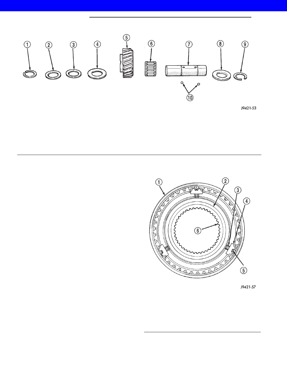
(6) Verify synchro springs, struts and detent balls

are all in place (Fig. 48).

Fig. 47 REVERSE IDLER COMPONENTS

1 - SNAP RING
2 - FLAT WASHER
3 - WAVE WASHER
4 - THRUST WASHER
5 - REVERSE IDLER GEAR
6 - IDLER GEAR BEARING

7 - IDLER SHAFT
8 - THRUST WASHER
9 - SNAP RING
10 - THRUST WASHER LOCKBALLS

Fig. 48 SYNCHRONIZER COMPONENTS

1 - SLEEVE
2 - HUB SHOULDER
3 - SPRING (3)
4 - STRUT (3)
5 - DETENT BALL (3)
6 - HUB

21s - 14

MANUAL NV 3550

XJ

MANUAL NV 3550 (Continued)

2001 JEEP CHEROKEE

OUTPUT SHAFT

Lubricate shaft, gears and bearings with recom-

mended lubricant during assembly. Petroleum jelly
can be used to hold parts in place. Check bearing
surfaces of output shaft for nicks or scratches.
Smooth surfaces with 320/400 grit emery cloth if nec-
essary. Apply oil to emery cloth and shaft surface
before polishing.

Inspect and replace any synchro ring if worn or

damage. Immerse each synchro ring in lubricant
before installation.

(1) Lubricate and install reverse gear needle bear-

ing on shaft (Fig. 49). Slide bearing up against shoul-
der on output shaft.

(2) Install reverse gear over needle bearing (Fig.

50).

(3) Install brass synchro ring on reverse gear (Fig.

51).

(4) Assemble fifth-reverse synchro hub, sleeve,

struts, springs and detent balls, if not previously
done.

CAUTION: One side of the hub has shoulders
around the hub bore, this side of the hub faces the
front of the shaft. One side of the sleeve is tapered
the tapered side faces the front of the shaft.

(5) Start fifth-reverse synchro assembly on output

shaft splines by hand. Then seat synchro onto shaft
with a press and Cup 6310-1 (Fig. 52).

Fig. 49 REVERSE GEAR BEARING

1 - REVERSE GEAR BEARING
2 - SHOULDER

Fig. 50 REVERSE GEAR

1 - REVERSE GEAR

Fig. 51 REVERSE SYNCHRO

1 - REVERSE GEAR
2 - SYNCHRO RING

Fig. 52 FIFTH-REVERSE SYNCHRO ASSEMBLY

1 - SPACER
2 - PRESS RAM
3 - REVERSE GEAR
4 - FIFTH-REVERSE SYNCHRO ASSEMBLY
5 - SPECIAL TOOL 6310–1
6 - PRESS BLOCKS
7 - OUTPUT SHAFT

XJ

MANUAL NV 3550

21s - 15

MANUAL NV 3550 (Continued)

2001 JEEP CHEROKEE

(6) Install new fifth-reverse hub snap ring (Fig.

53) and verify the snap ring is seated.

NOTE: Snap rings are available in thicknesses from
2.00 mm to 2.20 mm (0.078 to 0.086 in.). Install
thickest snap ring that will fit in shaft groove.

(7) Install fifth gear synchro ring in synchro hub

and sleeve (Fig. 54).

(8) Install fifth gear bearing, spreading bearing

only enough to clear shoulder on output shaft (Fig.
55). Verify bearing is properly seated.

(9) Install fifth gear on shaft and onto bearing

(Fig. 56).

(10) Invert output shaft and set the shaft in Cup

6310-1 so that fifth gear is seated on the tool (Fig.
57).

Fig. 53 FIFTH/REVERSE SYNCHRO HUB SNAP RING

1 - FIFTH-REVERSE SYNCHRO ASSEMBLY
2 - SNAP RING
3 - PRESS BED
4 - PRESS BLOCKS

Fig. 54 FIFTH GEAR SYNCHRO RING

1 - FIFTH-SPEED SYNCHRO RING
2 - FIFTH-REVERSE SYNCHRO ASSEMBLY

Fig. 55 FIFTH GEAR BEARING

1 - SHAFT SHOULDER
2 - FIFTH GEAR BEARING

Fig. 56 FIFTH GEAR

1 - FIFTH GEAR
2 - BEARING

21s - 16

MANUAL NV 3550

XJ

MANUAL NV 3550 (Continued)

2001 JEEP CHEROKEE

(11) Install first gear bearing on output shaft (Fig.

57). Verify bearing is seated on shaft shoulder and is
properly joined.

(12) Install first gear on shaft and over bearing

with bearing synchro cone facing up (Fig. 58).

(13) Install first gear synchro ring (Fig. 59).

(14) Assemble 1-2 synchro hub sleeve, springs,

struts and detent balls.

CAUTION: The 1-2 synchro hub and sleeve can be
installed backwards. One side of the synchro sleeve
is marked First Gear Side. Verify this side of the
sleeve is facing first gear.

(15) Start 1-2 synchro assembly on shaft by hand

(Fig. 60). Verify synchro sleeve is properly positioned.

Fig. 57 FIRST GEAR BEARING

1 - FIRST GEAR BEARING
2 - SHAFT SHOULDER
3 - SPECIAL TOOL
4 - PRESS BLOCKS

Fig. 58 FIRST GEAR

1 - FIRST GEAR
2 - SPECIAL TOOL 6310–1
3 - BEARING

Fig. 59 FIRST GEAR SYNCHRO RING

1 - FIRST GEAR SYNCHRO RING
2 - CUP
3 - FIRST GEAR

Fig. 60 STARTING 1-2 SYNCHRO ON SHAFT

1 - 1-2 SYNCHRO ASSEMBLY
2 - SPECIAL TOOL
3 - FIRST GEAR SIDE OF SYNCHRO SLEEVE

XJ

MANUAL NV 3550

21s - 17

MANUAL NV 3550 (Continued)

2001 JEEP CHEROKEE


Content   ..  796  797  798  799   ..