Jeep XJ. Manual - part 475


  Index      Jeep     Jeep XJ - service repair manual 2001 year


Search            


Content   ..  473  474  475  476   ..


Jeep XJ. Manual - part 475


(3) Remove the trim panel and waterdam from

door inner panel.

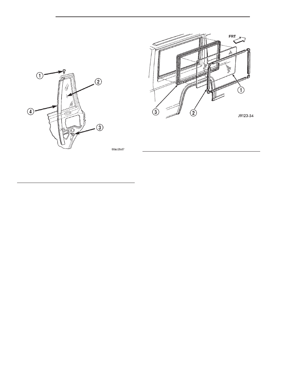
(4) Remove the screws attaching the division bar/

glass to the door (Fig. 7).

(5) Tilt the division bar/glass forward and remove

it from the door.

INSTALLATION

(1) Position the division bar/glass in the door.
(2) Install the screws attaching the division bar/

glass to the door. Finger tighten the screws.

(3) Tighten the upper screw to 6 N·m (5 ft-lbs)

torque.

(4) Tighten the lower screw to 6 N·m (5 ft-lbs)

torque.

(5) Install the beltline weatherstrip.
(6) Install the door waterdam and trim panel.

REAR QUARTER WINDOW GLASS

REMOVAL

(1) If equipped, remove the quarter window reveal

molding (Fig. 8).

(2) Remove the quarter window interior trim cov-

ers.

(3) Separate the weatherstrip seal lip from the

window opening flanges. Use a pry tool and carefully
push the window glass and seal outward.

(4) Remove the weatherstrip seal and window

glass from window opening.

(5) Remove the weatherstrip seal from the window

glass.

INSTALLATION

(1) Clean the original sealant from the weather-

strip channels and window opening flanges.

(2) Apply a 4-mm (1/6-in) diameter bead of sealant

to the window channel in the weatherstrip seal.

(3) Install the weatherstrip on the window glass.

Install the seal installation cord in the window open-
ing flange channel (Fig. 9) as follows:

• Moisten a length of 6-mm (1/4-in) diameter cord

with a soap and water solution.

• Ensure that the cord is long enough to go all the

way around the perimeter of the weatherstrip.

• Insert the cord into the window opening flange

channel in the weatherstrip seal.

(4) Apply a 6-mm (1/4-in) diameter bead of sealant

to the window opening flanges.

(5) For two-door vehicles, apply a 3-mm (1/8-in)

diameter bead of sealant at the quarter panel appli-
que and liftgate pillar seam.

(6) Position the quarter window glass and the

weatherstrip seal in the window opening (Fig. 10)
with the free ends of the cord inside the vehicle (Fig.
11).

(7) Pull on each end of the cord to pull the weath-

erstrip seal channel lip over the window opening
flanges.

(8) Test the vent window for water leaks.
(9) Install the interior trim cover.
(10) If equipped, install the quarter window reveal

molding.

Fig. 7 Division Bar/Stationary Glass

1 – UPPER SCREW
2 – GLASS
3 – LOWER SCREW
4 – DIVISION BAR

Fig. 8 Quarter Window Reveal Molding, Glass and

Seal

1 – GLASS
2 – REVEAL MOULDING
3 – WEATHERSTRIP SEAL

23 - 10

BODY

XJ

REMOVAL AND INSTALLATION (Continued)

LIFTGATE GLASS

REMOVAL

(1) Open liftgate.
(2) Remove liftgate trim panel.
(3) Disconnect heated backlite (HBL) connector.
(4) Remove wiper arm.
(5) Remove CHMSL lens.
(6) Using a razor knife, slide the blade between

the liftgate glass and the inboard edge of the reveal
molding.

(7) Cut around the interior perimeter of the reveal

molding and severe the cap of the reveal molding.

(8) Using a cold knife, cut urethane bonding from

around liftgate glass. A pneumatic cutting device can
be used if available.

(9) Separate glass from Liftgate.

INSTALLATION

CAUTION: Open a window before installing glass.
This will avoid pressurizing the passenger compart-
ment. If a door or liftgate is slammed before ure-
thane is cured, water leaks can result.

(1) Trim the urethane from the liftgate glass open-

ing flanges. Leave a 3 mm (0.1 in.) level base of ure-
thane on the flanges.

(2) Starting in the corners, press reveal molding

onto glass.

(3) Place replacement glass into liftgate opening

and position glass in the center of the opening
against flange.

(4) Verify the glass lays evenly against the fence at

the sides, top and bottom. If not, the flange must be
formed to the shape of the new glass.

(5) Using a grease pencil or equivalent, make ref-

erences marks on the glass and body.

(6) Remove replacement glass from liftgate open-

ing.

(7) Position the glass inside up on a suitable work

surface.

Fig. 9 Weatherstrip Seal and Cord Installation

1 – WINDOW GLASS
2 – INSTALLATION CORD END
3 – WEATHERSTRIP SEAL
4 – WINDOW GLASS
5 – WEATHERSTRIP SEAL
6 – INSTALLATION CORD

Fig. 10 Quarter Window With Vent

1 – QUARTER WINDOW W/VENT
2 – WEATHERSTRIP SEAL
3 – INSTALLATION CORD

Fig. 11 Quarter Window Glass and Seal Installation

1 – WEATHERSTRIP
2 – 1/4-INCH DIAMETER CORD (POSITION IN WEATHERSTRIP

GLASS CHANNEL)

XJ

BODY

23 - 11

REMOVAL AND INSTALLATION (Continued)

WARNING: DO NOT USE SOLVENT BASED GLASS
CLEANER

TO

CLEAN

WINDSHIELD

BEFORE

APPLYING

GLASS

PREP AND

PRIMER.

POOR

ADHESION CAN RESULT.

(8) Clean inside of glass with Mopar Glass Cleaner

and lint-free cloth.

(9) Apply PVC (vinyl) primer 25 mm (1 in.) wide

around edge of glass. Wipe with clean/dry lint-free
cloth.

(10) If necessary, apply fence primer around edge

of fence. Allow at least eighteen minutes drying time.

(11) Apply a 10 mm (0.4 in.) bead of urethane

around glass border.

(12) Position glass into liftgate opening and refer-

ence marks.

(13) Push the glass inward until the reveal mold-

ing is seated onto the liftgate frame. Use care to
avoid excessive squeeze-out of adhesive.

(14) Open windows to prevent pressure build-up

while the urethane is curing.

(15) Apply 150 mm (6 in.) lengths of 50 mm (2 in.)

masking tape spaced 250 mm (10 in.) apart to hold
glass in place until urethane cures.

(16) Install the wiper arm.
(17) Install CHMSL lens.
(18) Connect heated backlite (HBL) connector.
(19) After urethane has cured, remove tape strips

and water test to verify repair.

(20) Install liftgate trim panel.

23 - 12

BODY

XJ

REMOVAL AND INSTALLATION (Continued)

SEATS

TABLE OF CONTENTS

page

page

REMOVAL AND INSTALLATION

HEAD RESTRAINT SLEEVE. . . . . . . . . . . . . . . . . 13
HEAD RESTRAINT COVER . . . . . . . . . . . . . . . . . 14
BUCKET SEAT . . . . . . . . . . . . . . . . . . . . . . . . . . . 15
BUCKET SEAT TRACK. . . . . . . . . . . . . . . . . . . . . 15
BUCKET SEAT PLATFORM . . . . . . . . . . . . . . . . . 15
BUCKET SEATBACK COVER . . . . . . . . . . . . . . . . 16
BUCKET SEATBACK . . . . . . . . . . . . . . . . . . . . . . 16
BUCKET SEAT CUSHION COVER . . . . . . . . . . . . 17

BUCKET SEAT RECLINER . . . . . . . . . . . . . . . . . . 17
REAR SEAT CUSHION. . . . . . . . . . . . . . . . . . . . . 17
REAR SEATBACK . . . . . . . . . . . . . . . . . . . . . . . . 18
REAR SEAT CUSHION COVER . . . . . . . . . . . . . . 19
REAR SEATBACK LATCH STRIKER AND

BUMPER. . . . . . . . . . . . . . . . . . . . . . . . . . . . . . 19

REAR SEATBACK COVER . . . . . . . . . . . . . . . . . . 20

SPECIAL TOOLS

SPECIAL TOOLS—SEATS . . . . . . . . . . . . . . . . . . 20

REMOVAL AND INSTALLATION

HEAD RESTRAINT SLEEVE

REMOVAL

NOTE: When replacing a head restraint sleeve, the
retaining tabs on the sleeve will be damaged during
the removal process. Check the availability of
replacement parts before servicing.

(1) Raise head restraint to the full up position.
(2) Turn head restraint lock thumbwheel to release

head restraint and pull head restraint upward to
remove from seat back.

(3) Insert head restraint sleeve extractor (special

tool 6773) (Fig. 1) and (Fig. 2) into the seat back.

(4) The retaining tabs are positioned on each side

of the sleeve, when inserting the extractor, ensure
that the flat of the collar is facing the side of the
seatback (Fig. 3).

(5) Using a small hammer, tap extractor down-

ward to release sleeve retaining tab.

(6) Remove extractor tool from sleeve, rotate tool

180 degrees (Fig. 4) and repeat steps 3 and 4.

(7) Remove extractor tool from sleeve and remove

sleeve from seat back.

Fig. 1 Head Restraint Sleeve Extractor

1 – SEAT BACK
2 – HEAD RESTRAINT SLEEVE
3 – EXTRACTOR TOOL 6773

XJ

BODY

23 - 13


Content   ..  473  474  475  476   ..