Jeep XJ. Manual - part 385


  Index      Jeep     Jeep XJ - service repair manual 2001 year


Search            


Content   ..  383  384  385  386   ..


Jeep XJ. Manual - part 385


ADAPTER HOUSING—4WD

(1) Install rear bearing in adapter housing. Use

wood hammer handle or wood dowel to tap bearing
into place.

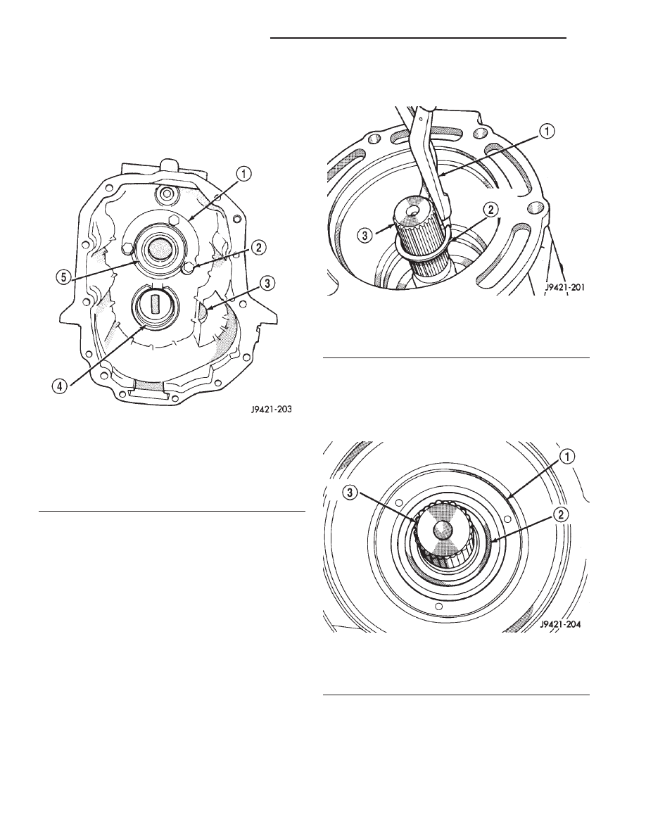
(2) Position rear bearing retainer in adapter hous-

ing (Fig. 106).

(3) Apply Mopar

t Gasket Maker, or equivalent, to

threads, bolt shanks and under hex heads of bearing
retainer bolts (Fig. 107).

(4) Apply liberal quantity of petroleum jelly to

countershaft rear bearing and bearing race.

(5) Install countershaft rear bearing in bearing

race (Fig. 102).

CAUTION: The

countershaft

bearings

can

be

installed backwards if care is not exercised. Be
sure the large diameter side of the roller retainer
faces the countershaft and the small diameter side
faces the race and housing (Fig. 102).

(6) Apply extra petroleum jelly to hold counter-

shaft rear bearing in place when housing is installed.

(7) Apply light coat of petroleum jelly to shift shaft

bushing/bearing in adapter housing (Fig. 102).

(8) Install adapter housing on geartrain.

(9) Install rear bearing snap ring on output shaft

(Fig. 107).

(10) Lubricate lip of new rear seal (Fig. 108) with

Mopar

t Door Ease, or transmission fluid.

(11) Install new rear seal in adapter housing bore

with Installer C-3860-A. Be sure seal is fully seated
in housing bore (Fig. 108).

SHIFT SHAFT, SHAFT LEVER AND BUSHING AND SHIFT
SOCKET

(1) Before

proceeding,

verify

that

all

synchro

sleeves are in Neutral position (centered on hub).
Move sleeves into neutral if necessary.

Fig. 106 Preparing Adapter Housing For

Installation—4WD

1 – BEARING RETAINER
2 – RETAINER BOLTS (3)
3 – IDLER SHAFT NOTCH
4 – COUNTERSHAFT REAR BEARING RACE
5 – REAR BEARING

Fig. 107 Installing Rear Bearing Snap Ring—4WD

1 – HEAVY DUTY SNAP RING PLIERS
2 – REAR BEARING SNAP RING
3 – OUTPUT SHAFT

Fig. 108 Rear Seal Installation—4WD

1 – REAR SEAL
2 – SEAL LIP
3 – OUTPUT SHAFT

21 - 76

NV3550 MANUAL TRANSMISSION

XJ

DISASSEMBLY AND ASSEMBLY (Continued)

CAUTION: The transmission synchros must all be
in Neutral position for proper reassembly. Other-
wise, the housings, shift forks and gears can be
damaged during installation of the two housings.

(2) Install 3-4 shift fork in synchro sleeve (Fig.

109). Verify that groove in fork arm is aligned with
grooves in 1-2 and fifth-reverse fork arms as shown.

(3) Slide shift shaft through 3-4 shift fork (Fig.

110). Be sure shaft detent notches are to front.

(4) Assemble shift shaft shift lever and bushing

(Fig. 111). Be sure slot in bushing is facing up and
roll pin hole for lever is aligned with hole in shaft.

(5) Install assembled lever and bushing on shift

shaft (Fig. 112).

(6) Slide shift shaft through 1-2 and fifth-reverse

fork and into shift lever opening in rear housing (Fig.
113).

(7) Align shift socket with shaft and slide shaft

through socket and into shift shaft bearing in rear
housing (Fig. 114).

(8) Rotate shift shaft so detent notches in shaft are

facing the TOP of the transmission housing.

Fig. 109 Installing 3-4 Shift Fork

1 – 3–4 FORK
2 – ALIGN GROOVES IN FORK ARMS

Fig. 110 Shift Shaft Installation

1 – SHIFT SHAFT
2 – 3–4 FORK
3 – SHAFT DETENT NOTCHES

Fig. 111 Assembling Shift Shaft Lever And Bushing

1 – SHAFT LEVER
2 – LEVER BUSHING
3 – BUSHING LOCK PIN SLOT

Fig. 112 Installing Shift Shaft Lever And Bushing

1 – SHIFT SHAFT
2 – SHAFT LEVER AND BUSHING
3 – 3–4 FORK

XJ

NV3550 MANUAL TRANSMISSION

21 - 77

DISASSEMBLY AND ASSEMBLY (Continued)

CAUTION: Correct positioning of the shift shaft
detent notch is important. Both of the shaft roll pins
can be installed even when the shaft is 180° off. If
this occurs, the transmission will have to be disas-
sembled again to correct shaft alignment.

(9) Select correct new roll pin for shift shaft lever

(Fig. 115). Shaft lever roll pin is approximately 22
mm (7/8 in.) long. Shift socket roll pin is approxi-
mately 33 mm (1-1/4 in.) long.

(10) Align roll pin holes in shift shaft, lever and

bushing. Then start roll pin into shaft lever by hand
(Fig. 116).

(11) Seat shaft lever roll pin with pin punch (Fig.

117).

CAUTION: The shaft lever roll pin must be flush
with the surface of the lever. The lever bushing will
bind on the roll pin if the pin is not seated flush.

(12) Before proceeding, verify that lock pin slot in

lever bushing is positioned as shown (Fig. 117).

(13) Align roll pin holes in shift socket and shift

shaft. Then start roll pin into shift shaft by hand
(Fig. 118).

Fig. 113 Inserting Shaft Into Lever Opening In

Housing

1 – SHIFT SHAFT

Fig. 114 Shift Socket Installation

1 – SHIFT SOCKET
2 – SHIFT SHAFT

Fig. 115 Roll Pin Identification—Shaft Lever And

Shift Socket

1 – SHAFT LEVER ROLL PIN
2 – SHIFT SOCKET ROLL PIN

Fig. 116 Starting Roll Pin In Shift Shaft Lever

1 – SHAFT LEVER ROLL PIN (

7

8

” LONG)

2 – LEVER AND BUSHING

21 - 78

NV3550 MANUAL TRANSMISSION

XJ

DISASSEMBLY AND ASSEMBLY (Continued)

(14) Seat roll pin in shift socket with pin punch.

Roll pin must be flush with socket after installation
(Fig. 119).

(15) Verify that notches in shift fork arms are

aligned. Realign arms if necessary.

FRONT HOUSING AND INPUT SHAFT BEARING RETAINER

(1) If previously removed, install input shaft bear-

ing in front housing bore (Fig. 120). Install snap ring
and use plastic mallet to seat bearing. Bearing goes
in from front side of housing only.

Fig. 117 Correct Seating Of Shift Shaft Lever Roll

Pin

1 – BUSHING LOCK PIN SLOT
2 – SEAT ROLL PIN FLUSH WITH LEVER

Fig. 118 Starting Roll Pin In Shift Socket

1 – ROLL PIN
2 – SHIFT SOCKET
3 – SHIFT SHAFT

Fig. 119 Seating Shift Socket Roll Pin

1 – PIN PUNCH
2 – SHIFT SOCKET
3 – SEAT ROLL PIN FLUSH
4 – SHIFT SOCKET

Fig. 120 Input Shaft Bearing And Countershaft Front

Bearing

1 – INPUT SHAFT BEARING
2 – COUNTERSHAFT FRONT BEARING
3 – SHIFT SHAFT BUSHING

XJ

NV3550 MANUAL TRANSMISSION

21 - 79

DISASSEMBLY AND ASSEMBLY (Continued)


Content   ..  383  384  385  386   ..