Jeep XJ. Manual - part 354


  Index      Jeep     Jeep XJ - service repair manual 2001 year


Search            


Content   ..  352  353  354  355   ..


Jeep XJ. Manual - part 354


The battery input also provides the voltage that is

needed to keep the PCM memory alive. The memory
stores Diagnostic Trouble Code (DTC) messages.
Trouble codes will still be stored even if the battary
voltage is lost.

SENSOR RETURN—ECM/PCM INPUT (ANALOG
GROUND)

DESCRIPTION

Sensor Return provides a low noise Analog ground

reference for all system sensors.

IGNITION CIRCUIT SENSE—ECM/PCM INPUT

DESCRIPTION

The ignition circuit sense input signals the ECM

and PCM that the ignition (key) switch has been
turned to the ON position. This signal initiates the
glow plug control routine to begin the “pre–heat”
cycle.

IGNITION CIRCUIT SENSE—PCM INPUT

The ignition circuit sense input signals the PCM

that the ignition (key) switch has been turned to the
ON position. This signal initiates the glow plug con-
trol routine to begin the “pre–heat” cycle.

POWER GROUND

DESCRIPTION

Provides a common ground for power devices (sole-

noid and relay devices).

NEEDLE MOVEMENT OR INTRUMENTED FIRST
INJECTOR—ECM INPUT

DESCRIPTION

This input from the ECM supplies a constant 30

mA electrical current source for the first injector sen-
sor. It will vary the voltage to this sensor when it
senses a mechanical movement within the injector
needle (pintle) of the number–1 cylinder fuel injector.
When this voltage has been determined by the ECM,
it will then control an output to the fuel timing sole-
noid (the fuel timing solenoid is located on the fuel
injection pump). Also refer to Fuel Injection Pump for
additional information.

The first injector sensor is a magnetic (inductive)

type.

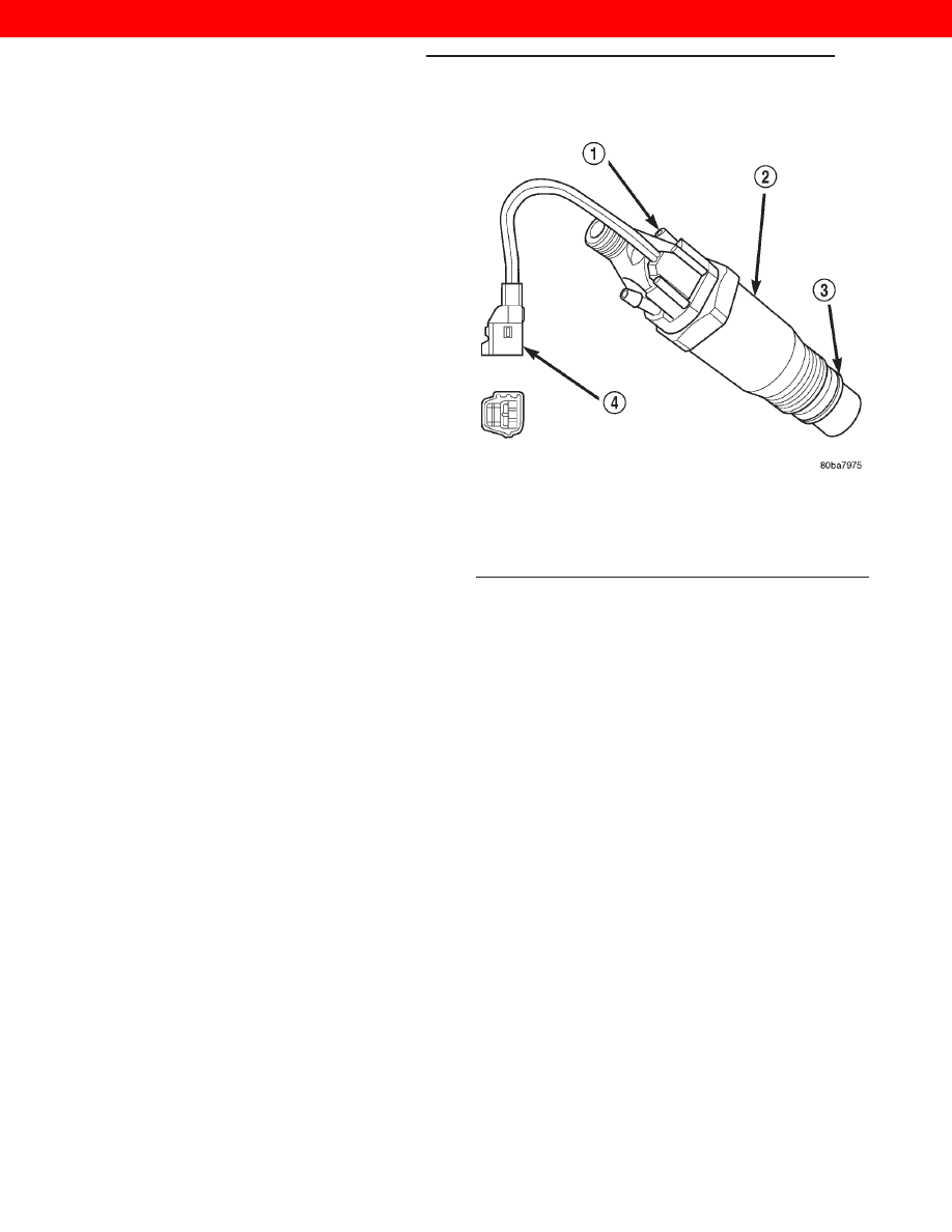
The first injector sensor is used only on the fuel

injector for the number–1 cylinder (Fig. 4). It is not
used on the injectors for cylinders number 2, 3, or 4.

FUEL INJECTOR SENSOR—GROUND

DESCRIPTION

Provides a low noise ground for the fuel injector

sensor only.

ENGINE COOLANT TEMPERATURE SENSOR—
ECM/PCM INPUT

DESCRIPTION

The 0–5 volt input from this sensor tells the ECM

and PCM the temperature of the engine coolant.
Based on the voltage received at the ECM, it will
then determine operation of the fuel timing solenoid,
glow plug relay, electrical vacuum modulator (emis-
sion component) and generator (charging system).

The sensor is located on the side of the #3 cylinder

head near the rear of fuel injection pump (Fig. 5).

ENGINE SPEED SENSOR—ECM INPUT

DESCRIPTION

The engine speed sensor is mounted to the trans-

mission bellhousing at the left/rear side of the engine
block (Fig. 6).

The engine speed sensor produces its own output

signal. If this signal is not received, the ECM will not
allow the engine to start.

The engine speed sensor input is used in conjunc-

tion with the first injector sensor to establish fuel
injection pump timing.

Fig. 4 Fuel Injector Sensor

1 – NEEDLE MOVEMENT SENSOR
2 – FUEL INJECTOR (NUMBER 1 CYLINDER ONLY)
3 – COPPER WASHER
4 – SENSOR CONNECTOR

14 - 26

FUEL SYSTEM—2.5L DIESEL ENGINE

XJ

DESCRIPTION AND OPERATION (Continued)

2000 JEEP CHEROKEE

The flywheel has four notches at its outer edge

(Fig. 7). Each notch is spaced equally every 90°. The
notches cause a pulse to be generated when they
pass under the speed sensor (Fig. 7). These pulses
are the input to the ECM. The input from this sensor
determines crankshaft position (in degrees) by moni-
toring the notches.

The sensor also generates an rpm signal to the

ECM. This signal is used as an input for the control

of the generator field, vehicle speed control, and
instrument panel mounted tachometer.

If the engine speed sensor should fail, the system

is unable to compensate for the problem and the car
will stop.

AIR CONDITIONING (A/C) CONTROLS—ECM
INPUTS

DESCRIPTION

The A/C control system information applies to fac-

tory installed air conditioning units.

A/C REQUEST SIGNAL: When either the A/C or

Defrost mode has been selected and the A/C low and
high–pressure switches are closed, an input signal is
sent to the ECM. The ECM uses this input to cycle
the A/C compressor through the A/C relay.

If the A/C low or high–pressure switch opens, the

ECM will not receive an A/C request signal. The
PCM will then remove the ground from the A/C relay.
This will deactivate the A/C compressor clutch. Also,
if the engine coolant reaches a temperature outside
normal of its normal range, or it overheats, the ECM
will deactivate the A/C clutch.

Fig. 5 Engine Coolant Temperature Sensor Location

1 – PCM ENGINE COOLANT TEMPERATURE (ECT) SENSOR
2 – ECM ENGINE COOLANT TEMPERATURE (ECT) SENSOR
3 – ECM ECT SENSOR HARNESS CONNECTOR
4 – PCM ECT SENSOR HARNESS CONNECTOR

Fig. 6 Engine Speed Sensor Location

1 – ENGINE SPEED SENSOR
2 – GROMMET
3 – MOUNTING BOLT(S)
4 – LEFT REAR OF ENGINE
5 – TRANSMISSION

Fig. 7 Speed Sensor Operation

1 – ENGINE SPEED SENSOR
2 – FLYWHEEL
3 – NOTCHES

XJ

FUEL SYSTEM—2.5L DIESEL ENGINE

14 - 27

DESCRIPTION AND OPERATION (Continued)

2000 JEEP CHEROKEE

BRAKE SWITCH—ECM INPUT

DESCRIPTION

When the brake light switch is activated, the ECM

receives an input indicating that the brakes are
being applied. After receiving this input, the ECM is
used to control the speed control system. There is a
Primary and a Secondary brake switch. The Second-
ary brake switch is closed until the brake pedal is
pressed.

DATA LINK CONNECTOR—PCM AND ECM
INPUT AND OUTPUT

The 16–way data link connector (diagnostic scan

tool connector) links the Diagnostic Readout Box
(DRB) scan tool with the PCM and ECM. The data
link connector is located under the instrument panel
near the left body side cowl panel on left hand drive
vehicles (Fig. 8). And near the right body side cowl
panel on right hand drive vehicles (Fig. 9).

VEHICLE SPEED SENSOR—ECM INPUT

The vehicle speed sensor is located in the transfer

case extension housing (Fig. 10). The sensor input is
used by the ECM to determine vehicle speed and dis-
tance traveled.

The speed sensor generates 8 pulses per sensor

revolution. These signals, in conjunction with a
closed throttle signal from the accelerator pedal posi-
tion sensor, indicate an idle deceleration to the ECM.
When the vehicle is stopped at idle, a released pedal
signal is received by the ECM (but a speed sensor
signal is not received).

In addition to determining distance and vehicle

speed, the output from the sensor is used to control
speed control operation.

SPEED CONTROL—ECM INPUT

DESCRIPTION

The speed control system provides five separate

inputs to the ECM: On/Off, Set, Resume/Accel, Cancel,
and Decel.. The On/Off input informs the ECM that the
speed control system has been activated. The Set input

Fig. 8 Data Link Connector Location – LHD

1 – 16–WAY DATA LINK CONNECTOR

Fig. 9 Data Link Connector Location –RHD

1 – DATA LINK CONNECTOR

Fig. 10 Vehicle Speed Sensor—4 Wheel Drive

1 – 4WD TRANSFER CASE EXTENSION
2 – VEHICLE SPEED SENSOR
3 – SENSOR ELECTRICAL CONNECTOR

14 - 28

FUEL SYSTEM—2.5L DIESEL ENGINE

XJ

DESCRIPTION AND OPERATION (Continued)

2000 JEEP CHEROKEE

informs the ECM that a fixed vehicle speed has been
selected. The Resume input indicates to the ECM that
the previous fixed speed is requested.

Speed control operation will start at 50 km/h–142

km/h (35–85 mph). The upper range of operation is
not restricted by vehicle speed. Inputs that effect
speed control operation are vehicle speed sensor and
accelerator pedal position sensor.

Refer to Group 8H for further speed control infor-

mation.

ASD RELAY—ECM INPUT

DESCRIPTION

A 12 volt signal at this input indicates to the ECM

that the ASD relay has been activated. The ASD
relay is located in the PDC. The PDC is located next
to the battery in the engine compartment. For the
location of the relay within the PDC, refer to label on
PDC cover.

This input is used only to sense that the ASD relay

is energized. If the ECM does not see 12 volts (+) at
this input when the ASD relay should be activated, it
will set a Diagnostic Trouble Code (DTC).

FIVE VOLT POWER—ECM/PCM OUTPUT

DESCRIPTION

This circuit supplies approximately 5 volts to

power the Accelerator Pedal Position Sensor, and the
Boost Pressure Sensor.

ENGINE COOLANT GAUGE—PCM OUTPUT

DESCRIPTION

Refer to the Instrument Panel and Gauges group

for additional information.

ENGINE OIL PRESSURE GAUGE—PCM
OUTPUT

DESCRIPTION

Refer to the Instrument Panel and Gauges group

for additional information.

GLOW PLUG LAMP—PCM OUTPUT

DESCRIPTION

The Glow Plug lamp (malfunction indicator lamp)

illuminates on the message center each time the igni-
tion (key) switch is turned on. It will stay on for
about two seconds as a bulb test.

SPEED CONTROL—PCM OUTPUTS

DESCRIPTION

These two circuits control the fuel quantity actua-

tor to regulate vehicle speed. Refer to Group 8H for
Speed Control information.

AIR CONDITIONING RELAY—ECM OUTPUT

DESCRIPTION

This circuit controls a ground signal for operation

of the A/C clutch relay. Also refer to Air Conditioning
(A/C) Controls—ECM Input for additional informa-
tion.

The A/C relay is located in the Power Distribution

Center (PDC). The PDC is located next to the battery
in the engine compartment. For the location of the
relay within the PDC, refer to label on PDC cover.

TIMING SOLENOID—ECM OUTPUT

DESCRIPTION

The timing solenoid is located on the bottom of the

fuel injection pump (Fig. 12).

This 12(+) volt, pulse width modulated (duty–cycle)

output controls the amount of fuel timing (advance)
in the fuel injection pump. The higher the duty–cy-
cle, the lower the advance. The lower the duty–cycle,
the more advanced the fuel timing.

Fig. 11 Glow Plug Lamp Symbol

Fig. 12 Timing Solenoid

1 – FUEL INJECTION PUMP ASSEMBLY
2 – FUEL RETURN LINE
3 – FUEL SUPPLY LINE
4 – FUEL INJECTION PUMP 10–WAY CONNECTOR
5 – TIMING SOLENOID
6 – OVERFLOW VALVE

XJ

FUEL SYSTEM—2.5L DIESEL ENGINE

14 - 29

DESCRIPTION AND OPERATION (Continued)

2000 JEEP CHEROKEE


Content   ..  352  353  354  355   ..