Jeep XJ. Manual - part 353


  Index      Jeep     Jeep XJ - service repair manual 2001 year


Search            


Content   ..  351  352  353  354   ..


Jeep XJ. Manual - part 353


(3) Wipe seal area of tank clean and place a new

o-ring seal in position on pump.

(4) Position fuel reservoir module in tank with locknut.
(5) Tighten locknut to 75 N·m (55 ft. lbs.).
(6) Connect fuel lines.
(7) Plug in electrical connector. Slide connector

lock into position.

(8) Raise fuel tank, install bolts into fuel tank

straps and tighten.

(9) Lower vehicle on hoist.
(10) Connect negative cable from battery.
(11) Fill fuel tank. Check for leaks.
(12) Install fuel filler cap.

HIGH-PRESSURE LINES

All high–pressure fuel lines are of the same length and

inside diameter. Correct high–pressure fuel line usage
and installation is critical to smooth engine operation.

CAUTION: The high–pressure fuel lines must be
clamped securely in place in the holders. The lines
cannot contact each other or other components. Do
not attempt to weld high–pressure fuel lines or to
repair lines that are damaged. Only use the recom-
mended lines when replacement of high–pressure
fuel line is necessary.

REMOVAL

(1) Disconnect negative battery cable from battery.
(2) Remove the necessary clamps holding the lines

to the engine.

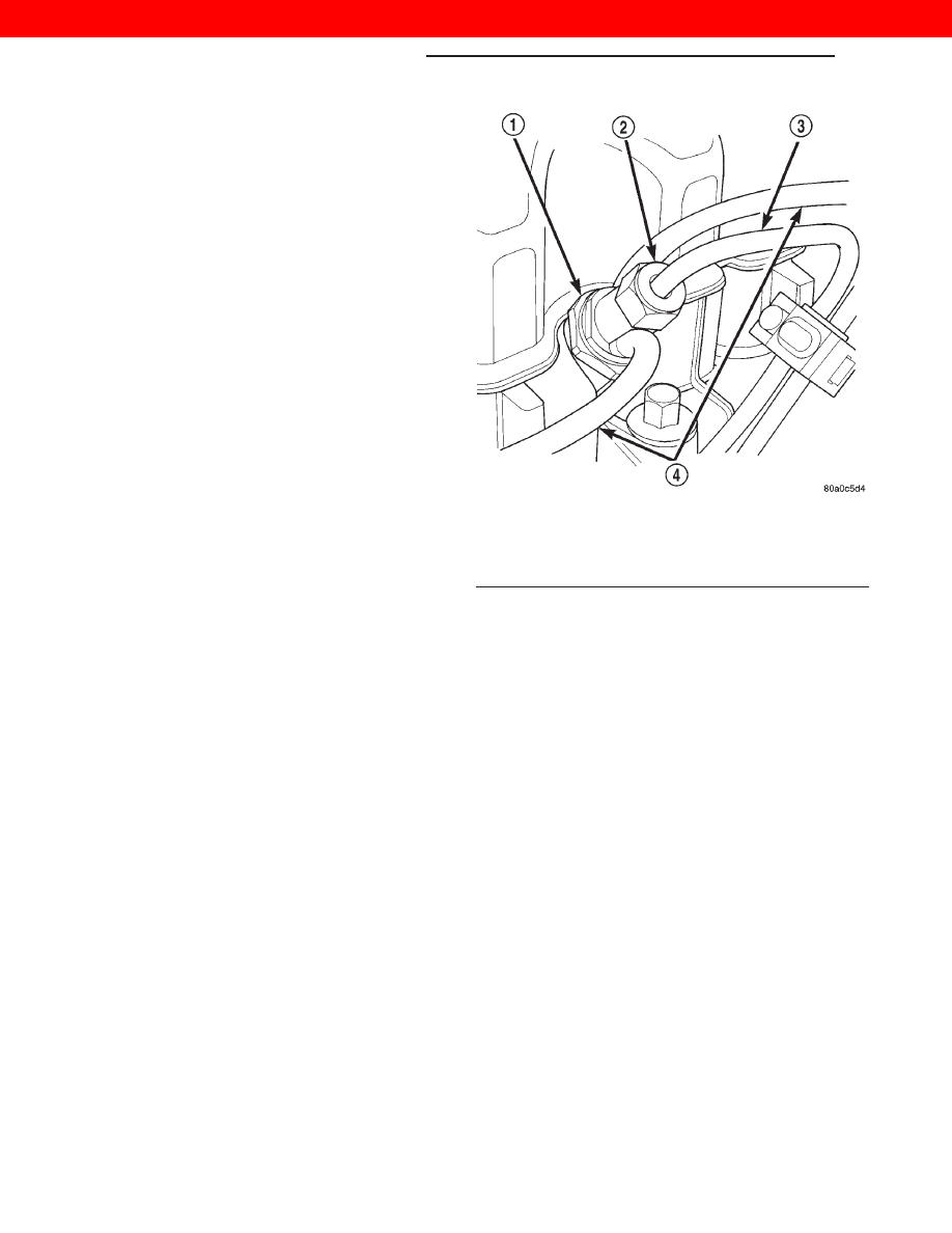
(3) Clean the area around each fuel line connec-

tion. Disconnect each line at the top of each fuel
injector (Fig. 45).

(4) Disconnect each high–pressure line fitting at

each fuel injection pump delivery valve.

(5) Very carefully remove each line from the engine.

Note the position (firing order) of each line while remov-
ing. Do not bend the line while removing.

CAUTION: Be sure that the high–pressure fuel lines
are installed in the same order that they were
removed. Prevent the injection pump delivery valve
holders from turning when removing or installing
high–pressure lines from injection pump.

INSTALLATION

(1) Carefully position each high–pressure fuel line

to the fuel injector and fuel injection pump delivery
valve holder in the correct firing order. Also position
each line in the correct line holder.

(2) Loosely install the line clamp/holder bolts.
(3) Tighten each line at the delivery valve to 19

N·m (168 in. lbs.) torque.

(4) Tighten each line at the fuel injector to 19 N·m

(168 in. lbs.) torque.

Be sure the lines are not contacting each

other or any other component.

(5) Bleed air from the fuel system. Refer to the Air

Bleed Procedure section of this group.

SPECIFICATIONS

FUEL TANK CAPACITY

75 Liters (20.0 Gals.)
Nominal refill capacities are shown. A variation

may be observed from vehicle to vehicle due to man-
ufacturing tolerances, ambient temperatures and
refill procedures.

IDLE SPEED

750 RPM

625 RPM with engine at normal oper-

ating temperature.

FUEL INJECTOR FIRING SEQUENCE

1–3–4–2

FUEL SYSTEM PRESSURE

Peak Injection Pressure/Fuel Injection Pump

Operating Pressure: 40,000–45,000 kPa (5801–
6526 psi).

Opening

Pressure

of

Fuel

Injector:

16,500–

17,300 kPa (2393–2509 psi).

Fig. 45 Fuel Lines at Fuel Injectors

1 – FUEL INJECTOR
2 – LINE FITTING
3 – HIGH-PRESSURE FUEL LINE
4 – FUEL DRAIN TUBES

14 - 22

FUEL SYSTEM—2.5L DIESEL ENGINE

XJ

REMOVAL AND INSTALLATION (Continued)

2000 JEEP CHEROKEE

FUEL INJECTION SYSTEM—2.5L DIESEL ENGINE

TABLE OF CONTENTS

page

page

DESCRIPTION AND OPERATION

FUEL INJECTION SYSTEM . . . . . . . . . . . . . . . . . 23
POWERTRAIN CONTROL MODULE (PCM) . . . . . 24
BOOST PRESSURE SENSOR . . . . . . . . . . . . . . . 25
VEHICLE THEFT ALARM . . . . . . . . . . . . . . . . . . . 25
BATTERY VOLTAGE—PCM INPUT. . . . . . . . . . . . 25
SENSOR RETURN—ECM/PCM INPUT

(ANALOG GROUND) . . . . . . . . . . . . . . . . . . . . . 26

IGNITION CIRCUIT SENSE—ECM/PCM INPUT . . 26
IGNITION CIRCUIT SENSE—PCM INPUT . . . . . . 26
POWER GROUND . . . . . . . . . . . . . . . . . . . . . . . . 26
NEEDLE MOVEMENT OR INTRUMENTED

FIRST INJECTOR—ECM INPUT . . . . . . . . . . . . 26

FUEL INJECTOR SENSOR—GROUND. . . . . . . . . 26
ENGINE COOLANT TEMPERATURE

SENSOR—ECM/PCM INPUT. . . . . . . . . . . . . . . 26

ENGINE SPEED SENSOR—ECM INPUT . . . . . . . 26
AIR CONDITIONING (A/C) CONTROLS—ECM

INPUTS. . . . . . . . . . . . . . . . . . . . . . . . . . . . . . . 27

BRAKE SWITCH—ECM INPUT. . . . . . . . . . . . . . . 28
DATA LINK CONNECTOR—PCM AND ECM

INPUT AND OUTPUT . . . . . . . . . . . . . . . . . . . . 28

VEHICLE SPEED SENSOR—ECM INPUT . . . . . . 28
SPEED CONTROL—ECM INPUT . . . . . . . . . . . . . 28
ASD RELAY—ECM INPUT . . . . . . . . . . . . . . . . . . 29
FIVE VOLT POWER—ECM/PCM OUTPUT . . . . . . 29
ENGINE COOLANT GAUGE—PCM OUTPUT . . . . 29
ENGINE OIL PRESSURE GAUGE—PCM

OUTPUT . . . . . . . . . . . . . . . . . . . . . . . . . . . . . . 29

GLOW PLUG LAMP—PCM OUTPUT . . . . . . . . . . 29
SPEED CONTROL—PCM OUTPUTS . . . . . . . . . . 29

AIR CONDITIONING RELAY—ECM OUTPUT . . . . 29
TIMING SOLENOID—ECM OUTPUT . . . . . . . . . . 29
TACHOMETER—PCM OUTPUT . . . . . . . . . . . . . . 30
GLOW PLUG RELAY—ECM OUTPUT . . . . . . . . . 30
GLOW PLUGS . . . . . . . . . . . . . . . . . . . . . . . . . . . 30
ELECTRIC VACUUM MODULATOR (EVM)—

ECM OUTPUT. . . . . . . . . . . . . . . . . . . . . . . . . . 31

DIAGNOSIS AND TESTING

DIESEL DIAGNOSTICS . . . . . . . . . . . . . . . . . . . . 31
ASD RELAY TEST . . . . . . . . . . . . . . . . . . . . . . . . 31
ENGINE SPEED SENSOR TEST . . . . . . . . . . . . . 31
ENGINE COOLANT TEMPERATURE SENSOR

TEST . . . . . . . . . . . . . . . . . . . . . . . . . . . . . . . . 31

GLOW PLUG TEST . . . . . . . . . . . . . . . . . . . . . . . 31
GLOW PLUG RELAY TEST . . . . . . . . . . . . . . . . . 33
RELAYS—OPERATION/TESTING . . . . . . . . . . . . . 34
BOOST / PRESSURE SENSOR . . . . . . . . . . . . . . 34
VEHICLE SPEED SENSOR TEST. . . . . . . . . . . . . 35
DIAGNOSTIC TROUBLE CODES . . . . . . . . . . . . . 35

REMOVAL AND INSTALLATION

ASD RELAY . . . . . . . . . . . . . . . . . . . . . . . . . . . . . 35
A/C CLUTCH RELAY . . . . . . . . . . . . . . . . . . . . . . 35
ENGINE SPEED SENSOR . . . . . . . . . . . . . . . . . . 35
ENGINE COOLANT TEMPERATURE SENSOR . . . 35
GLOW PLUGS . . . . . . . . . . . . . . . . . . . . . . . . . . . 35
GLOW PLUG RELAY . . . . . . . . . . . . . . . . . . . . . . 36
POWERTRAIN CONTROL MODULE (PCM) . . . . . 36
VEHICLE SPEED SENSOR . . . . . . . . . . . . . . . . . 37

SPECIFICATIONS

GLOW PLUG CURRENT DRAW . . . . . . . . . . . . . . 38
TORQUE CHART—2.5L DIESEL. . . . . . . . . . . . . . 38

DESCRIPTION AND OPERATION

FUEL INJECTION SYSTEM

DESCRIPTION

This section will cover components either regulated

or controlled by the ECM controller and the Power-
train Control Module (PCM). The fuel heater relay
and fuel heater are not operated by the ECM control-
ler or the PCM. These components are controlled by
the ignition (key) switch. All other fuel system elec-
trical components necessary to operate the engine
are controlled or regulated by the ECM controller,
which interfaces with the PCM. Refer to the follow-
ing description for more information.

Certain fuel system component failures may cause

a no start, or prevent the engine from running. It is
important to know that the ECM has a feature
where, if possible, it will ignore the failed sensor, set
a code related to the sensor, and operate the engine
in a “Limp Home” mode. When the ECM is operating
in a “Limp Home” mode, the Check Engine Lamp on
the instrument panel may be constantly illuminated,
and the engine will most likely have a noticeable loss
of performance. An example of this would be an
Accelerator Pedal Position Sensor failure, and in that
situation, the engine would run at a constant 1100
RPM, regardless of the actual position of the pedal.
This is the most extreme of the three “Limp Home”
modes.

When the Check Engine Lamp is illuminated con-

stantly with the key on and the engine running, it

XJ

FUEL SYSTEM—2.5L DIESEL ENGINE

14 - 23

2000 JEEP CHEROKEE

usually indicates a problem has been detected some-
where within the fuel system. The DRBIII scan tool
is the best method for communicating with the ECM
and PCM to diagnose faults within the system.

POWERTRAIN CONTROL MODULE (PCM)

DESCRIPTION

On LHD vehicles, the ECM is mounted behind the

lower Instrument Panel to the right of the accelera-
tor pedal (Fig. 1). On RHD vehicles, the ECM is
mounted behind the lower Instrument Panel to the
left of the clutch pedal. The Powertrain Control Mod-
ule (PCM) is mounted in the engine compartment.
(Fig. 2).

The ECM Controller is a pre–programmed, digital

computer. It will either directly operate or partially
regulate the:

• Speed Control

• Speed Control lamp

• Fuel Timing Solenoid

• Check Engine Light

• Glow Plug Relay

• Glow Plugs

• Glow Plug Lamp

• ASD Relay

• Air Conditioning

• Tachometer

• Electric Vacuum Modulator (EVM)
The ECM can adapt its programming to meet

changing operating conditions.

The ECM receives input signals from various

switches and sensors. Based on these inputs, the
ECM regulates various engine and vehicle operations
through different system components. These compo-
nents are referred to as ECM Outputs. The sensors
and switches that provide inputs to the ECM are
considered ECM Inputs.

ECM Inputs are:
• Air Conditioning Selection

• Theft Alarm

• ASD Relay

• Control Sleeve Position Sensor

• Fuel Temperature Sensor

• Mass Air Flow Sensor

• Accelerator Pedal Position Sensor

• Engine Coolant Temperature Sensor

• Low Idle Position Switch

• 5 Volt Supply

• Vehicle Speed Sensor

• Engine Speed/Crank Position Sensor (rpm)

• Needle Movement Sensor

• Starter Signal

• Brake Switch

• Speed Control Switch

• Power Ground

• Ignition (key) Switch Sense
ECM Outputs:
After inputs are received by the ECM and PCM,

certain sensors, switches and components are con-
trolled or regulated by the ECM and PCM. These are
considered ECM Outputs. These outputs are for:

• A/C Clutch Relay (for A/C clutch operation)

Fig. 1 ECM Location—LHD

1 – ECM HARNESS CONNECTOR C1
2 – ENGINE CONTROL MODULE (ECM)
3 – ECM HARNESS CONNECTOR C2
4 – ACCELERATOR PEDAL POSITION SENSOR

Fig. 2 PCM Location—LHD

1 – PCM HARNESS CONNECTOR C1
2 – PCM HARNESS CONNECTOR C2
3 – PCM HARNESS CONNECTOR C3
4 – POWERTRAIN CONTROL MODULE (PCM)

14 - 24

FUEL SYSTEM—2.5L DIESEL ENGINE

XJ

DESCRIPTION AND OPERATION (Continued)

2000 JEEP CHEROKEE

• Speed Control Lamp

• ASD Relay

• 5 Volts Supply

• Fuel Quantity Actuator

• Fuel Timing Solenoid

• Fuel Shutdown Solenoid

• Glow Plug Lamp

• Check Engine Lamp (“On/Off” signal)

• Electric Vacuum Modulator (EVM)

• Glow Plug Relay

• Tachometer
The PCM sends and recieves signals to and from

the ECM controller. PCM inputs are:

• Power Gound

• 5 Volts Supply

• Vehicle Speed Sensor

• Water-In-Fuel Sensor

• Coolant Temperature Sensor

• Low Coolant Sensor

• Sensor Return

• Fuel Level Sensor

• Oil Pressure Sensor

• Tachometer Signal

• Glow Plug Lamp

• Check Engine Lamp (“On/Off” signal)

• Brake On/Off Switch

• Battery Voltage

• ASD Relay
PCM Outputs:
• A/C On Signal

• Vehicle Theft Alarm “Ok to Run” signal

• Body Control Module CCD Bus (+)

• Body Control Module CCD Bus (–)

• Scan Tool Data Link Recieve

• Scan Tool Data Link Transmit

• Low Coolant Lamp

• Generator Control

BOOST PRESSURE SENSOR

DESCRIPTION

The Boost Pressure Sensor is mounted to the top of

the intake manifold (Fig. 3). It is a sensor that mea-
sures both manifold vacuum and turbo boost, and it
also contains an integrated intake air temperature
sensor. The Boost Pressure Sensor takes the place of
the Mass Air Flow (MAF). In the Intake Air Temper-
ature Sensor component, there is a ceramic element
that changes its resistance based on temperature.
The ceramic element is part of an electronic circuit
connected to the PCM, and has a voltage applied to
it. The ceramic element is exposed to the air inside
the intake. This air has a cooling effect on the
ceramic element, and its resistance changes. This
causes the voltage flowing through the intake air
temperature circuit to vary. The voltage signal pro-

duced by the Intake Air Temperature Sensor changes
inversely to the temperature, and is measured by the
PCM. As a general rule, when the temperature of the
air in the intake is high, the voltage signal produced
by the Intake Air Temperature Sensor is low. The
component of the Boost Pressure Sensor that mea-
sures manifold vacuum and turbo boost produces a
voltage signal that is proportional to the pressure in
the intake manifold. When the intake manifold pres-
sure is low, the voltage is low, and when the pressure
is high, the voltage is high. The PCM uses the volt-
age signals from the Boost Pressure Sensor, and the
Intake Air Temperature Sensor to determine the
amount of air flowing through the intake manifold.

VEHICLE THEFT ALARM

DESCRIPTION

The PCM can learn if the vehicle has a Vehicle

Theft Alarm (VTA) system. Once it detects the vehi-
cle having VTA, the controller can ONLY BE
USED ON VEHICLES WITH VTA.

If the PCM is put it on a vehicle without VTA the

Glow Plug Lamp will start to blink and the vehicle
will not start.

The PCM cannot be flashed to remove the VTA.

BATTERY VOLTAGE—PCM INPUT

DESCRIPTION

The battery voltage input provides power to the

PCM. It also informs the PCM what voltage level is
being supplied by the generator once the vehicle is
running.

Fig. 3 Boost Pressure Sensor Location

1 – BOOST PRESSURE SENSOR HARNESS CONNECTOR
2 – BOOST PRESSURE SENSOR

XJ

FUEL SYSTEM—2.5L DIESEL ENGINE

14 - 25

DESCRIPTION AND OPERATION (Continued)

2000 JEEP CHEROKEE


Content   ..  351  352  353  354   ..