Jeep XJ. Manual - part 322


  Index      Jeep     Jeep XJ - service repair manual 2001 year


Search            


Content   ..  320  321  322  323   ..


Jeep XJ. Manual - part 322


(2) Remove cylinder heads, refer to cylinder head

removal in this section.

(3) Raise vehicle on host.
(4) Remove oil pan, refer to oil pan removal in this

section.

(5) Remove top ridge of cylinder bores with a reli-

able ridge reamer before removing pistons from cyl-
inder block. Be sure to keep tops of pistons
covered during this operation
. Mark piston with
matching cylinder number.

(6) Pistons and connecting rods must be removed

from top of cylinder block. Rotate crankshaft so that
each connecting rod is centered in cylinder bore.

(7) Remove connecting rod cap. Install connecting

rod bolt protectors on connecting rod bolts. Push each
piston and rod assembly out of cylinder bore.

NOTE: Be careful not to nick crankshaft journals.

(8) After removal, install bearing cap on the mat-

ing rod.

PISTON PIN—REMOVAL

(1) Secure connecting rod in a soft jawed vice.
(2) Remove 2 clips securing piston pin.
(3) Push piston pin out of piston and connecting

rod.

PISTON RING—REMOVAL

(1) ID mark on face of upper and intermediate pis-

ton rings must point toward piston crown.

(2) Using a suitable ring expander, remove upper

and intermediate piston rings (Fig. 54).

(3) Remove the upper oil ring side rail, lower oil

ring side rail and then oil ring expander from piston.

(4) Carefully clean carbon from piston crowns,

skirts and ring grooves ensuring the 4 oil holes in
the oil control ring groove are clear.

PISTON RING FITTING

(1) Wipe cylinder bore clean. Insert ring and push

down with piston to ensure it is square in bore. The
ring gap measurement must be made with the ring
positioning at least 12 mm (0.50 in.) from bottom of
cylinder bore. Check gap with feeler gauge. Top com-
pression ring gap.25 to.50mm (.0098 to.0196 in.). Sec-
ond compression ring gap.25 to.35mm (.0098 to.0137
in.). Oil control ring gap.25 to.58mm (.0098 to.0228
in.).

(2) If ring gaps exceed dimension given, new rings

or cylinder liners must be fitted. Keep piston rings in
piston sets.

(3) Check piston ring to groove clearance (Fig. 56).

Top compression ring gap.08 to.130mm (.0031 to.0051
in.). Second compression ring gap.070 to.102mm
(.0027 to.0040 in.). Oil control ring gap.040 to.072mm
(.0015 to.0028 in.).

PISTON RINGS—INSTALLATION

(1) Install rings on the pistons using a suitable

ring expander (Fig. 57).

(2) Top compression ring is tapered and chromium

plated. The second ring is of the scraper type and
must be installed with scraping edge facing bottom of
the piston. The third is an oil control ring. Ring gaps
must be positioned, before inserting piston into the
liners, as follows (Fig. 59).

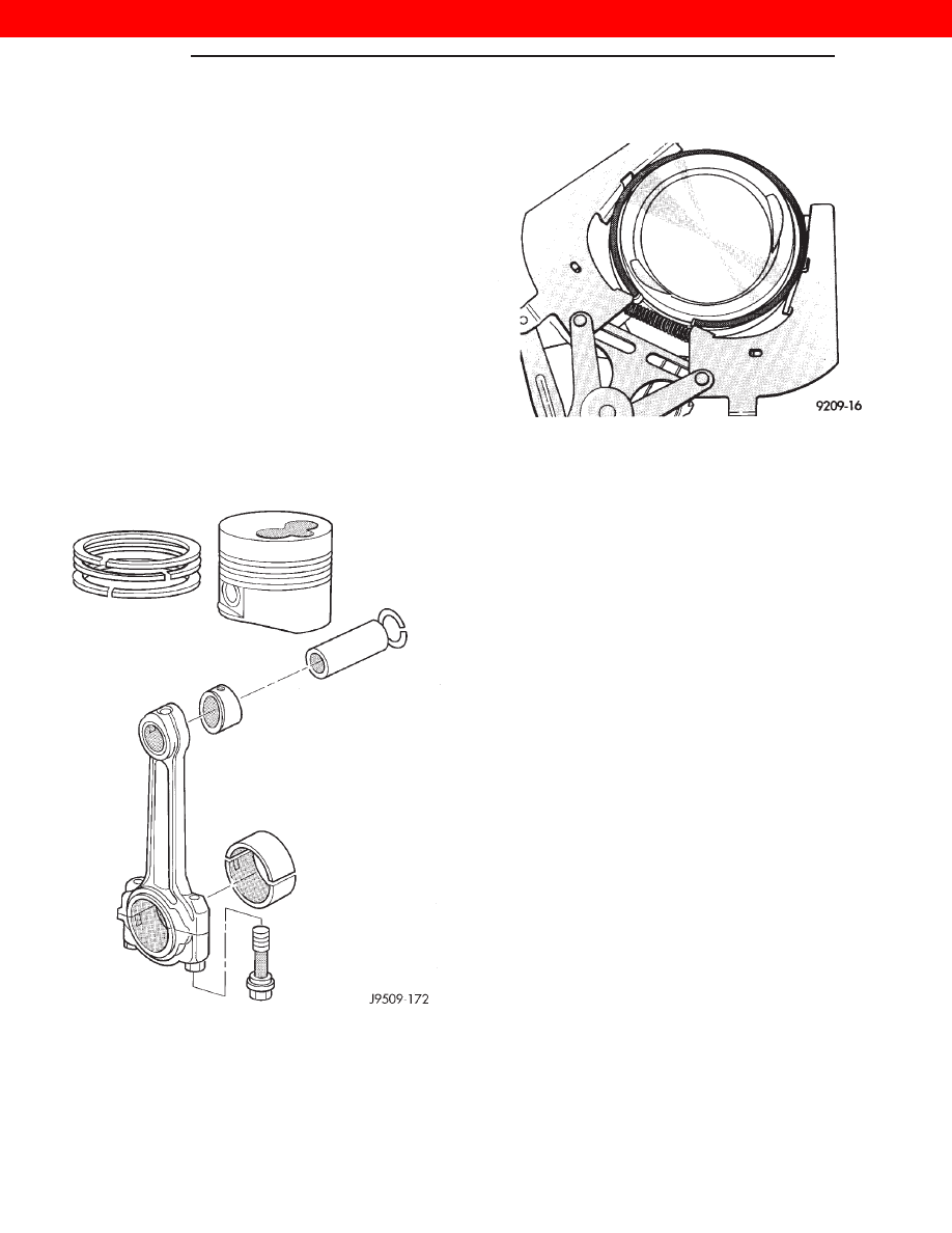
Fig. 53 Piston Assembly

Fig. 54 Piston Rings—Removing and Installing

9 - 36

ENGINE

XJ

REMOVAL AND INSTALLATION (Continued)

2000 JEEP CHEROKEE

(3) Top ring gap must be positioned at 30 degrees

to the right of the combustion chamber recess (look-
ing at the piston crown from above).

(4) Second piston ring gap should be positioned on

the opposite side of the combustion chamber recess.

(5) Oil control ring gap to be located 30 degrees to

the left of combustion chamber recess.

(6) When assembling pistons check that compo-

nents are installed in the same position as before dis-
assembly, determined by the numbers stamped on
the crown of individual pistons. Engine cylinders are
numbered starting from gear train end of the engine.
Face chamber recess side of piston towards
camshaft
. Therefore, the numbers stamped on con

rod big end should also face in the same direction. To
insert piston into cylinder use a ring compressor as
shown in (Fig. 57).

PISTON PIN INSTALLATION

(1) Secure connecting rod in soft jawed vice.
(2) Lubricate piston pin and piston with clean oil.
(3) Position piston on connecting rod.

CAUTION: Ensure combustion recess in piston
crown and the bearing cap numbers on the con-
necting rod are on the same side.

(4) Install piston pin.
(5) Install clips in piston to retain piston pin.
(6) Remove connecting rod from vice.

INSTALLATION

(1) Before installing pistons, and connecting rod

assemblies into the bore, be sure that compression
ring gaps are staggered so that neither is in line with
oil ring rail gap (Fig. 59).

Fig. 55 Ring Gap Measurement

1 – FEELER GAUGE

Fig. 56 Piston Ring to Groove Clearance

Fig. 57 Piston Rings—Removing and Installing

Fig. 58 Piston Ring Identification

XJ

ENGINE

9 - 37

REMOVAL AND INSTALLATION (Continued)

2000 JEEP CHEROKEE

(2) Before installing the ring compressor, make

sure the oil ring expander ends are butted and the
rail gaps located as shown in (Fig. 59).

(3) Immerse the piston head and rings in clean

engine oil, slide the ring compressor, over the piston
and tighten with the special wrench (Fig. 60).
Ensure position of rings does not change dur-
ing this operation
.

(4) Face chamber recess side of piston towards

camshaft.

NOTE: Be careful not to nick crankshaft journals.

(5) Rotate crankshaft so that the connecting rod

journal is on the center of the cylinder bore. Insert
rod and piston into cylinder bore and guide rod over
the crankshaft journal.

(6) Tap the piston down in cylinder bore, using a

hammer handle. At the same time, guide connecting
rod into position on connecting rod journal.

(7) Install rod caps. Install rod bolts and tighten to

29 N·m (21 ft. lb.) plus 60°.

CYLINDER WALL LINER ASSEMBLY

REMOVAL

(1) Remove cylinder heads.
(2) Remove Oil pan.
(3) Remove pistons.
(4) Use tool VM-1001 to remove liners (Fig. 61).

(5) Remove shims from cylinder liner or cylinder

block recess. Keep shims with each cylinder liner.

INSTALLATION

(1) Carefully clean residual LOCTITE from liner

and crankcase, and degrease the crankcase where it
comes into contact with the liners. Install the liners
in the crankcase as shown (A), rotating them back
and forth by 45° in order to guarantee correct posi-
tioning (Fig. 63).

(2) Measure the liner recess relative to block deck

with a dial indicator mounted on a special tool

Fig. 59 Piston Ring Gap Location

Fig. 60 Installing Piston

Fig. 61 Liner Removal Tool

9 - 38

ENGINE

XJ

REMOVAL AND INSTALLATION (Continued)

2000 JEEP CHEROKEE

VM-1010 A. All the measurements must be taken
on camshaft side
. Zero dial gauge on block deck.

(3) Move dial gauge to cylinder liner record read-

ing on dial gauge.

(4) Remove liner and special tool.
(5) Then select the correct shim thickness to give

proper protrusion (0.01 - 0.06 mm).

(6) Fit the shim and the O-rings onto the liner.
(7) Lubricate the lower liner location in the block.

Apply LOCTITE AVX to the corner of the liner seat.
Apply LOCTITE AVX uniformly to the upper part of
the liner at area.

(8) Fit the liners in the crankcase making sure

that the shim is positioned correctly in the seat. Lock
the liners in position using special tool (VM-1016)
and bolts (Fig. 64). Clean the residual LOCTITE on
the upper surface of the block deck.

(9) Recheck the liner protrusion. It should be 0.01

- 0.06 mm.

NOTE: A period of six hours must elapse between
the liners being installed and engine start-up. If
engine assembly is not continued after liner instal-
lation, the liners need to be clamped for twelve
hours minimum.

Fig. 63 Liner Installation

Fig. 62 Liner Inspection

XJ

ENGINE

9 - 39

REMOVAL AND INSTALLATION (Continued)

2000 JEEP CHEROKEE


Content   ..  320  321  322  323   ..