Jeep XJ. Manual - part 317


  Index      Jeep     Jeep XJ - service repair manual 2001 year


Search            


Content   ..  315  316  317  318   ..


Jeep XJ. Manual - part 317


CAUTION: Do not rotate the steering shaft while
removed from the gearbox input shaft. Damage to
the steering column clockspring will occur.

(4) Remove the oil filter adaptor retaining bolt and

remove oil filter and adaptor from the vehicle.

(5) Remove the engine mount upper sill plate nuts

(Fig. 12).

(6) Remove the engine mount throughbolt nut only.

Leave the bolt installed at this time.

(7) Position a jack stand and raise the weight off

the right engine mount.

(8) Remove

the

(4)

trackbar

support

bracket

retaining bolts and remove the bracket.

(9) Remove the (4) engine mount bracket bolts

from the engine block.

(10) Remove the remaining engine mount lower

sill plate bolt.

(11) Remove the engine mount through bolt.
(12) Remove the right engine mount from the vehi-

cle.

INSTALLATION—RIGHT SIDE

(1) Position the engine mount and bracket in posi-

tion and install the engine mount through bolt and
nut, leaving them loose at this time.

(2) Install, but do not torque the engine mount

lower sill plate bolts and the trackbar support
bracket bolts.

(3) Install the (4) engine mount bracket to engine

block retaining bolts. Torque bolts to 61 N·m (45 ft.
lbs.).

(4) Torque the engine mount lower sill plate bolts

to 41 N·m (30 ft. lbs.).

(5) Torque the larger trackbar support bracket

bolts to 125 N·m (92 ft. lbs.).

(6) Install the oil filter and adaptor on the engine.

Torque oil filter adaptor retaining bolt to 69 N·m (51
ft. lbs.).

(7) Remove the jack stand.
(8) Install the engine mount upper sill plate nuts.

Torque to 41 N·m (30 ft. lbs.).

(9) Torque the engine mount throughbolt nut to 65

N·m (48 ft. lbs.).

(10) Install the steering shaft and torque the

pinchbolt to 49 N·m (36 ft. lbs.).

(11) Lower the vehicle from the hoist.
(12) Connect the negative battery cable.

REMOVAL—LEFT SIDE

(1) Disconnect the negative battery cable.
(2) Remove the refrigerant line support bracket

bolt from the upper radiator support crossmember..

(3) Remove the A/C filter-drier assembly support

bracket nuts from the left fenderwell.

(4) Disconnect A/C compressor electrical connector

(Fig. 13).

(5) Raise the vehicle on a hoist.
(6) Remove the engine mount throughbolt nut only

(Fig. 13). Leave the bolt installed at this time.

(7) Loosen the (4) H-Block retaining bolts, Do not

remove the bolts at this time.

Fig. 11 Left Engine Mount Sill Plate Nuts

1 – SILL PLATE NUTS
2 – STEERING SHAFT
3 – ENGINE MOUNT

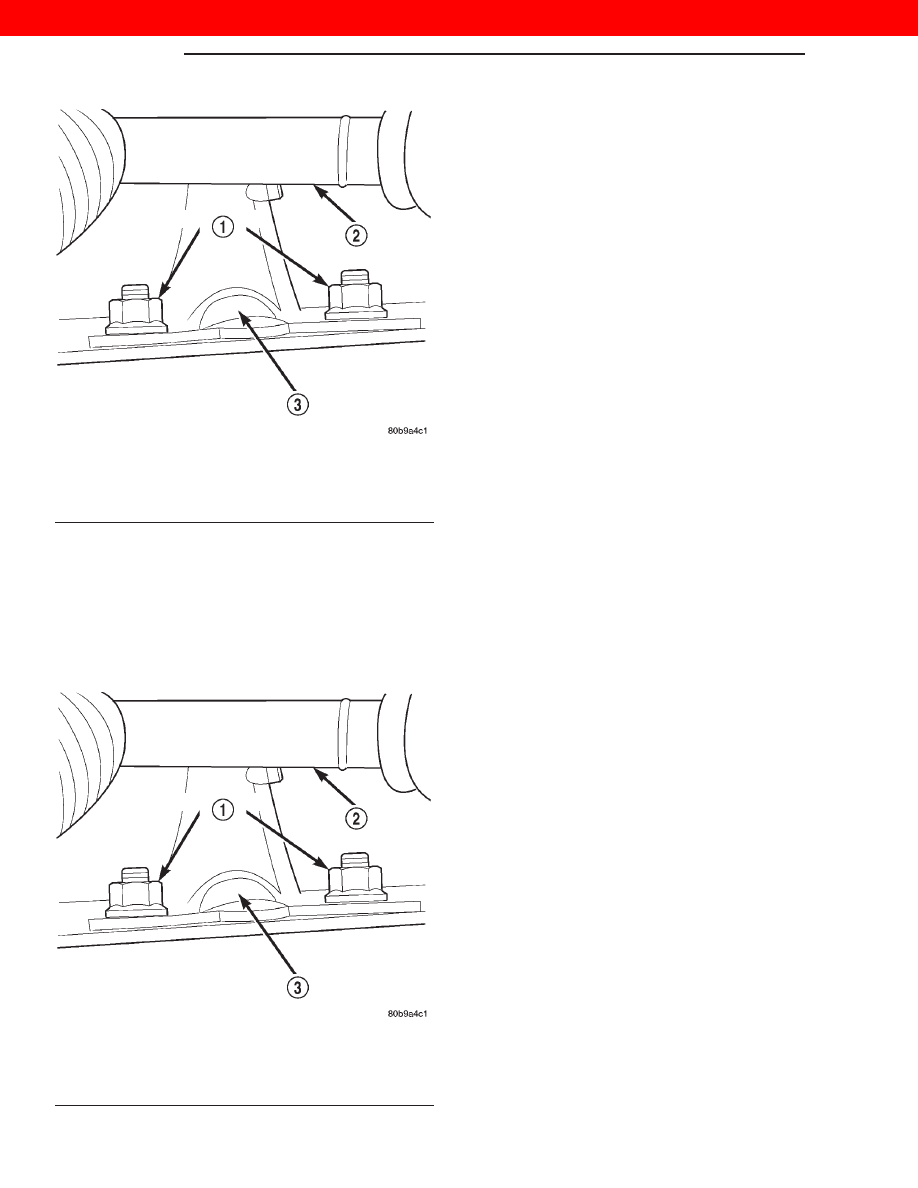
Fig. 12 Right Engine Mount Sill Plate Nuts

1 – SILL PLATE NUTS
2 – STEERING SHAFT
3 – ENGINE MOUNT

9 - 16

ENGINE

XJ

REMOVAL AND INSTALLATION (Continued)

2000 JEEP CHEROKEE

NOTE: Mark the position of the H-Block in relation
to the power steering pump and A/C Compressor so
it may be installed in its original position.

(8) Remove the (2) H-Block retaining bolts from

the power steering pump side of the block (Fig. 13).

(9) Support the A/C Compressor with mechanics

wire before proceeding to the next step.

(10) Remove the (4) A/C Compressor mounting

bolts (Fig. 13).

(11) Remove the remaining (2) bolts from H-Block

and remove the H-Block from the compressor.

(12) Position a jack stand and raise the weight off

the left engine mount.

(13) Remove the (2) engine mount upper sill plate

nuts.

(14) Remove the (4) engine mount bracket bolts

from the engine block.

(15) Remove the (2) engine mount lower sill plate

bolts.

(16) Remove the engine mount troughbolt.
(17) Remove the left engine mount from the vehi-

cle.

INSTALLATION—LEFT SIDE

(1) Position the engine mount and bracket in posi-

tion and install the engine mount through bolt and
nut, leaving them loose at this time.

(2) Install, but do not torque engine mount lower

sill plate bolts.

(3) Install the (4) engine mount bracket to engine

block retaining bolts. Torque to 61 N·m (45 ft. lbs.).

(4) Torque the (2) lower engine mount sill plate

bolts to 41 N·m (30 ft. lbs.).

(5) Install the (2) engine mount upper sill plate

nuts. Torque to 41 N·m (30 ft. lbs.).

(6) Remove the jack stand.

(7) Position the H-Block and the A/C Compressor

in there original positions and install the retaining
bolts (Fig. 14).

(8) Torque the A/C Compressor mounting bolts to

41 N·m (30 ft. lbs.) (Fig. 14).

(9) Torque all the H-Block bolts to 18 N·m (159 in.

lbs.) (Fig. 14).

(10) Torque the engine mount throughbolt nut to

65 N·m (48 ft. lbs.) (Fig. 14).

(11) Lower the vehicle from the hoist.
(12) Install the refrigerant line support bracket.
(13) Install the A/C filter-drier support bracket.
(14) Connect the negative battery cable.

Fig. 13 A/C Compressor Position & Orientation

1 – A/C COMPRESSOR MOUNTING BOLTS
2 – LEFT ENGINE MOUNT THROUGHBOLT NUT
3 – H BLOCK BOLTS
4 – COUPLER PINCH BOLT
5 – COMPRESSOR ELECTRICAL CONNECTOR

Fig. 14 A/C Compressor Position & Orientation

1 – A/C COMPRESSOR MOUNTING BOLTS
2 – LEFT ENGINE MOUNT THROUGHBOLT NUT
3 – H BLOCK BOLTS
4 – COUPLER PINCH BOLT
5 – COMPRESSOR ELECTRICAL CONNECTOR

XJ

ENGINE

9 - 17

REMOVAL AND INSTALLATION (Continued)

2000 JEEP CHEROKEE

2.5L DIESEL ENGINE

REMOVAL

(1) Disconnect both of the battery cables and

remove the battery.

(2) Mark the hinge locations on the hood for align-

ment reference during installation.

CAUTION: Wrap the appropriate size drillbit with
masking tape 1/4 inch from tip. This will prevent
damaging the hood outer panel when drilling out
the rivets retaining the hood latch cable control
assembly.

(3) Drill out the rivets retaining the hood latch

cable control assembly.

(4) Remove the hood latch assemblies from the

hood.

(5) Disconnect and remove the engine compart-

ment lamp.

(6) With assistance from another person, remove

the hood

(7) Cover both of the fenders and the grill opening

panel to prevent paint damage.

(8) Remove the battery tray.
(9) Disconnect the radiator cooling fan electrical.
(10) Remove the manual cooling fan and let set

inside of the fan shroud.

(11) If equipped, recover the refrigerant. Refer to

Group 24, Heating and Air Conditioning for the pro-
cedure.

(12) Disconnect the suction and discharge lines

and remove the lines from the vehicle.

(13) Disconnect the breather hose and remove the

air filter outlet hose from the vehicle (Fig. 15).

(14) Disconnect the oil pressure sensor electrical

connector (Fig. 15).

(15) Disconnect the EGR vacuum supply hose from

the engine (Fig. 15).

(16) Remove the coolant reservoir cap.
(17) Drain the cooling system. Refer to Group 7,

Cooling System for the procedure.

(18) Remove the upper and lower radiator hoses

from the engine.

(19) Remove the innercooler inlet and outlet hoses

from the engine (Fig. 15).

(20) Remove the coolant reservoir supply hose

from the engine (Fig. 15).

(21) On L. H. D. vehicles, disconnect the heater

core coolant supply and the brake vacuum supply
hoses from the engine.

(22) On R. H. D. vehicles, disconnect the heater

core coolant supply and the brake vacuum supply
hoses from the right side of the engine compartment.
Remove the line assembly retaining bolt and bracket

from the rear of the rocker cover and position the
assembly out of the way.

(23) Working inside of the vehicle, remove the cen-

ter console. Refer to Group 23, Body for the proce-
dure.

(24) Remove the shifter boot seal.
(25) Disconnect the shifter from the transmission
(26) Raise the vehicle on a hoist.
(27) Remove the lower fan shroud retaining bolts

and remove the lower fan shroud panel.

(28) Remove the engine ground wire (Fig. 16).
(29) Remove the right and left engine mount

throughbolt nuts only. Do not remove the bolts at
this time (Fig. 16).

(30) Drain the transmission fluid. Refer to Group

21, Transmission and Transfer Case for the proce-
dure.

(31) Mark the position of the front and rear drive-

shafts in relation to there companion flanges.

(32) Remove the front driveshaft. Refer to Group

3, Differential and Driveline for the procedure.

(33) Remove the rear driveshaft. Refer to Group 3,

Differential and Driveline for the procedure.

(34) Disconnect the exhaust system at the (3) bolt

flange (Fig. 17).

Fig. 15 LHD Engine Compartment — Diesel

1 – HEATER CORE COOLANT SUPPLY HOSES
2 – INNERCOOLER OUTLET HOSE
3 – AIR FLITER OUTLET HOSE
4 – EGR VACUUM SUPPLY HOSE
5 – OIL PRESSURE SENSOR CONNECTOR
6 – INNERCOOLER INLET HOSE
7 – COOLANT SUPPLY HOSE

9 - 18

ENGINE

XJ

REMOVAL AND INSTALLATION (Continued)

2000 JEEP CHEROKEE

(35) Remove the exhaust system support clamp

(Fig. 17).

(36) Remove the clutch slave cylinder from the

clutch housing (Fig. 18).

(37) Remove the (3) nuts retaining the transfer

case shift linkage and position the linkage aside (Fig.
19).

Fig. 16 Engine Ground Wire Location

1 – RIGHT ENGINE MOUNT THROUGHBOLT NUT
2 – ENGINE GROUND WIRE
3 – OIL PAN

Fig. 17 Exhaust System Inlet Pipe Connection

1 – OIL PAN
2 – EXHAUST INLET PIPE FLANGE RETAINING BOLTS
3 – EXHAUST SYSTEM SUPPORT CLAMP

Fig. 18 Clutch Slave Cylinder

1 – CLUTCH SLAVE CYLINDER
2 – CLUTCH SLAVE CYLINDER RETAINING NUTS
3 – FRONT DRIVESHAFT

Fig. 19 Transfer Case Shift Linkage — 4x4

1 – FRONT DRIVESHAFT
2 – SHIFTER LINKAGE RETAINING NUTS
3 – TRANSFER CASE
4 – TRANSMISSION

XJ

ENGINE

9 - 19

REMOVAL AND INSTALLATION (Continued)

2000 JEEP CHEROKEE


Content   ..  315  316  317  318   ..