Jeep XJ. Manual - part 293


  Index      Jeep     Jeep XJ - service repair manual 2001 year


Search            


Content   ..  291  292  293  294   ..


Jeep XJ. Manual - part 293


(13) Install the intake and exhaust manifolds

(refer to Group 11, Exhaust System and Intake Man-
ifold for the proper procedures).

(14) Install the fuel supply line. Push until a

“click” is heard. Reinstall latch clip.

(15) If equipped, attach the power steering pump

and bracket.

(16) Install the push rods, rocker arms, pivots and

bridges in the order they were removed.

(17) Install the engine cylinder head cover.
(18) Attach the air conditioning compressor mount-

ing bracket to the engine cylinder head and block.
Tighten the bolts to 40 N·m (30 ft. lbs.) torque.

(19) Attach the air conditioning compressor to the

bracket. Tighten the bolts to 27 N·m (20 ft. lbs.)
torque.

CAUTION: The accessory drive belt must be routed
correctly. Incorrect routing can cause the water
pump to turn in the opposite direction causing the
engine to overheat.

(20) Install the accessory drive belt and correctly

tension the belt (refer to Group 7, Cooling System for
the proper procedure).

(21) Install the air cleaner assembly.
(22) Connect the hoses to the thermostat housing

and fill the cooling system to the specified level (refer
to Group 7, Cooling Systems for the proper proce-
dure).

(23) Install the coolant temperature sending unit

connector.

(24) Connect negative cable to battery.
(25) Connect the upper radiator hose and heater

hose at the thermostat housing.

(26) Fill the cooling system. Check for leaks.

WARNING: USE EXTREME CAUTION WHEN THE
ENGINE IS OPERATING. DO NOT STAND IN DIRECT

LINE WITH THE FAN. DO NOT PUT HANDS NEAR
THE PULLEYS, BELTS OR FAN. DO NOT WEAR
LOOSE CLOTHING.

(27) Operate the engine with the radiator cap off.

Inspect for leaks and continue operating the engine
until the thermostat opens. Add coolant, if required.

CYLINDER HEAD

DISASSEMBLY

(1) Use

Valve

Spring

Compressor

Tool

MD-998772A and compress each valve spring.

(2) Remove the valve locks, retainers, springs and

valve stem oil seals. Discard the oil seals.

(3) Use an Arkansas smooth stone or a jewelers

file to remove any burrs on the top of the valve stem,
especially around the groove for the locks.

(4) Remove the valves, and place them in a rack in

the same order as removed.

ASSEMBLY

(1) Thoroughly clean the valve stems and the valve

guide bores.

(2) Lightly lubricate the stem.
(3) Install the valve in the original valve guide

bore.

(4) Install the replacement valve stem oil seals on

the valve stems. If the 0.381 mm (0.015 inch) over-
size valve stems are used, oversize oil seals are
required.

(5) Position the valve spring and retainer on the

engine cylinder head and compress the valve spring
with Valve Spring Compressor Tool MD-998772A.

(6) Install the valve locks and release the tool.
(7) Tap the valve spring from side to side with a

hammer to ensure that the spring is properly seated
at the engine cylinder head. Also tap the top of the
retainer to seat the valve locks.

HYDRAULIC TAPPETS

REMOVAL

Retain all the components in the same order as

removed.

(1) Remove the engine cylinder head cover (refer to

procedure earlier in this section)

(2) Remove the bridge and pivot assemblies and

rocker arms by removing the capscrews at each
bridge. Alternately loosen each capscrew, one turn at
a time, to avoid damaging the bridges.

(3) Remove the push rods.
(4) Remove the tappets through the push rod open-

ings in the cylinder head with a Hydraulic Valve
Tappet Removal/Installation Tool (Fig. 60).

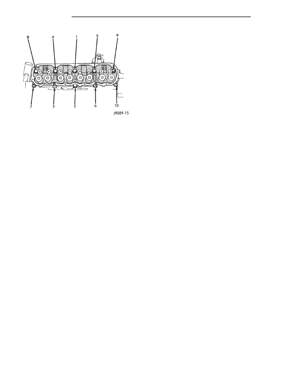
Fig. 59 Engine cylinder head Bolt Tightening

Sequence

9 - 40

2.5L ENGINE

XJ

REMOVAL AND INSTALLATION (Continued)

INSTALLATION

It is not necessary to charge the tappets with

engine oil. They will charge themselves within a very
short period of engine operation.

(1) Dip each tappet in Mopar Engine Oil Supple-

ment, or equivalent.

(2) Use Hydraulic Valve Tappet Removal/Installa-

tion Tool to install each tappet in the same bore from
where it was originally removed.

(3) Install the push rods in their original locations.
(4) Install the rocker arms and bridge and pivot

assemblies at their original locations. Loosely install
the capscrews at each bridge.

(5) Tighten the capscrews alternately, one turn at

a time, to avoid damaging the bridges. Tighten the
capscrews to 28 N·m (21 ft. lbs.) torque.

(6) Install the engine cylinder head cover.

VIBRATION DAMPER

REMOVAL

(1) Disconnect negative cable from battery.
(2) Remove the serpentine drive belt and fan

shroud.

(3) Remove the vibration damper retaining bolt

and washer.

(4) Use Vibration Damper Removal Tool 7697 to

remove the damper from the crankshaft (Fig. 61).

INSTALLATION

(1) Apply Mopar Silicone Rubber Adhesive Sealant

to the keyway in the crankshaft and insert the key.

With the key in position, align the keyway on the
vibration damper hub with the crankshaft key and
tap the damper onto the crankshaft.

(2) Install the vibration damper retaining bolt and

washer.

(3) Tighten the damper retaining bolt to 108 N·m

(80 ft. lbs.) torque.

(4) Install the serpentine drive belt and tighten to

the specified tension (refer to Group 7, Cooling Sys-
tems for the proper specifications and procedures).

(5) Connect negative cable to battery.

TIMING CASE COVER OIL SEAL

REMOVAL

This procedure is done with the timing case cover

installed.

(1) Disconnect negative cable from battery.
(2) Remove the serpentine drive belt.
(3) Remove the vibration damper.
(4) Remove the radiator shroud.
(5) Carefully remove the oil seal. Make sure seal

bore is clean.

INSTALLATION

(1) Position the replacement oil seal on Timing

Case Cover Alignment and Seal Installation Tool
6139 with seal open end facing inward. Apply a light
film of Perfect Seal, or equivalent, on the outside
diameter of the seal. Lightly coat the crankshaft with
engine oil.

(2) Position the tool and seal over the end of the

crankshaft and insert a draw screw tool into Seal
Installation Tool 6139 (Fig. 62). Tighten the nut
against the tool until it contacts the cover.

Fig. 60 Hydraulic Valve Tappet Removal/Installation

Tool

1 – HYDRAULIC VALVE TAPPET REMOVAL/INSTALLATION TOOL

Fig. 61 Vibration Damper Removal Tool 7697

1 – VIBRATION DAMPER REMOVAL TOOL
2 – WRENCH

XJ

2.5L ENGINE

9 - 41

REMOVAL AND INSTALLATION (Continued)

(3) Remove the tools. Apply a light film of engine

oil on the vibration damper hub contact surface of
the seal.

(4) Apply Mopar Silicone Rubber Adhesive Sealant

to the keyway in the crankshaft and insert the key.
With the key inserted in the keyway in the crank-
shaft, install the vibration damper, washer and bolt.
Lubricate and tighten the bolt to 108 N·m (80 ft. lbs.)
torque.

(5) Install the serpentine belt and tighten to the

specified tension (refer to Group 7, Cooling Systems
for the proper specifications and procedures).

(6) Install the radiator shroud.
(7) Connect negative cable to battery.

TIMING CASE COVER

REMOVAL

(1) Disconnect battery negative cable.
(2) Remove accessory drive belt (Refer to Group

07, Cooling System for proper procedure)

(3) Remove the accessory drive brackets that are

attached to the timing case cover.

(4) Remove the fan and hub assembly and remove

the fan shroud.

(5) Remove the A/C compressor (if equipped) and

generator bracket assembly from the engine cylinder
head and move to one side.

(6) Remove the vibration damper (Fig. 63).
(7) Remove the oil pan-to-timing case cover bolts

and timing case cover-to-cylinder block bolts.

(8) Remove the timing case cover and gasket from

the engine.

(9) Pry the crankshaft oil seal from the front of the

timing case cover (Fig. 63).

INSTALLATION

(1) Clean the timing case cover, oil pan and cylin-

der block gasket surfaces.

(2) Install a new crankshaft oil seal in the timing

case cover. The open end of the seal should be toward
the inside of the cover. Support the cover at the seal
area while installing the seal. Force it into position
with Seal Installation Tool 6139.

(3) Position the gasket on the cylinder block.
(4) Position the timing case cover on the oil pan

gasket and the cylinder block.

(5) Insert Timing Case Cover Alignment and Seal

Installation Tool 6139 in the crankshaft opening in
the cover (Fig. 64).

Fig. 62 Timing Case Cover Oil Seal Installation

1 – SEAL INSTALLATION TOOL
2 – DRAW SCREW TOOL

Fig. 63 Timing Case Cover Components

1 – TIMING CASE COVER
2 – OIL SLINGER
3 – CRANKSHAFT OIL SEAL
4 – VIBRATION DAMPER PULLEY

Fig. 64 Timing Case Cover Alignment and Seal

Installation Tool 6139

1 – TIMING CASE COVER ALIGNMENT AND SEAL

INSTALLATION TOOL

9 - 42

2.5L ENGINE

XJ

REMOVAL AND INSTALLATION (Continued)

(6) Install the timing case cover-to-cylinder block

and the oil pan-to-timing case cover bolts.

(7) Tighten the 1/4 inch cover-to-block bolts to 7

N·m (60 in. lbs.) torque. Tighten the 5/16 inch front
cover-to-block bolts to 22 N·m (192 in. lbs.) torque.
Tighten the oil pan-to-cover bolts to 9.5 N·m (84 in.
lbs.) torque.

(8) Remove the cover alignment tool.
(9) Apply a light film of engine oil on the vibration

damper hub contact surface of the seal.

(10) Apply Mopar Silicone Rubber Adhesive Seal-

ant to the keyway in the crankshaft and insert the
key. With the key inserted in the keyway in the
crankshaft, install the vibration damper, washer and
bolt. Lubricate and tighten the bolt to 108 N·m (80 ft.
lbs.) torque.

(11) Install the A/C compressor (if equipped) and

generator bracket assembly.

(12) Install the engine fan and hub assembly and

shroud.

(13) Install the accessory drive belt and tighten to

obtain the specified tension.

(14) Connect negative cable to battery.

TIMING CHAIN AND SPROCKETS

The chain drive system ie equipped with a timing

chain tensioner which reduces noise and prolongs
timing chain life. In addition, it compensates for
wear and temperature changes on the valve train for
proper engine operation.

REMOVAL

(1) Disconnect negative cable from battery.
(2) Remove the fan and shroud.
(3) Remove the serpentine drive belt.
(4) Remove the crankshaft vibration damper.
(5) Remove the timing case cover.
(6) Rotate crankshaft until the “0” timing mark is

closest to and on the center line with camshaft
sprocket timing mark (Fig. 65).

(7) Remove the oil slinger from the crankshaft.
(8) Remove

the

camshaft

retaining

bolt

and

remove the sprockets and chain as an assembly (Fig.
66).

(9) To replace the timing chain tensioner, the oil

pan must be removed.

INSTALLATION

(1) Turn the tensioner lever to the unlocked (down)

position (Fig. 67).

(2) Pull the tensioner block toward the tensioner

lever to compress the spring. Hold the block and turn
the tensioner lever to the lock position (Fig. 67).

(3) Apply Mopar Silicone Rubber Adhesive Sealant

to the keyway in the crankshaft and insert the key.
With the key in the crankshaft keyway, install the

crankshaft, camshaft sprockets and timing chain.
Ensure the timing marks on the sprockets are prop-
erly aligned (Fig. 65).

(4) Install the camshaft sprocket retaining bolt

and washer. Tighten the bolt to 108 N·m (80 ft. lbs.)
torque.

(5) To verify correct installation of the timing

chain, turn the crankshaft to position the camshaft
sprocket timing mark as shown in (Fig. 68). Count
the number of chain pins between the timing marks
of both sprockets. There must be 20 pins.

(6) Turn the chain tensioner lever to the unlocked

(down) position (Fig. 67).

(7) Install the oil slinger.
(8) Replace the oil seal in the timing case cover.
(9) Install the timing case cover and gasket.

Fig. 65 Crankshaft—Camshaft Alignment

1 – TIMING MARKS

Fig. 66 Camshaft and Crankshaft Sprockets and

Chain

1 – CAMSHAFT SPROCKET
2 – CRANKSHAFT SPROCKET
3 – CHAIN

XJ

2.5L ENGINE

9 - 43

REMOVAL AND INSTALLATION (Continued)


Content   ..  291  292  293  294   ..