Jeep XJ. Manual - part 291


  Index      Jeep     Jeep XJ - service repair manual 2001 year


Search            


Content   ..  289  290  291  292   ..


Jeep XJ. Manual - part 291


(6) Remove the upper radiator hose and coolant

recovery hose (Fig. 48).

(7) Remove the fan shroud (Fig. 48).

(8) Remove the radiator/condenser (if equipped

with air conditioning).

(9) Remove fan assembly and install a 5/16 x 1/2-

inch SAE capscrew through fan pulley into water
pump flange. This will maintain the pulley and
water pump in alignment when crankshaft is rotated.

(10) Disconnect the heater hoses.
(11) Disconnect the throttle cable, speed control

cable

(if

equipped)

and

transmission

cable

(if

equipped).

(12) Disconnect the body ground at the firewall.
(13) Disconnect the wires from the starter motor

solenoid.

(14) Disconnect all fuel injection harness connec-

tions.

WARNING: THE FUEL SYSTEM IS UNDER A CON-
STANT

PRESSURE

(EVEN

WITH

THE

ENGINE

TURNED OFF). BEFORE DISCONNECTING FUEL
LINES, THE FUEL SYSTEM PRESSURE MUST BE
RELEASED.

(15) Perform

fuel

pressure

release

procedure.

(refer to Group 14, Fuel System for the proper proce-
dure).

(16) Remove latch clip and disconnect the quick-

connect fuel line at the fuel rail

(17) Recover refrigerant (if equipped with A/C).

(Refer to group 24, Heating and Air Conditioning for
proper procedures.)

(18) Disconnect suction/discharge hose from A/C

compressor and cap off ports to prevent intrusion of
foreign material or refrigerant oil loss.

(19) Remove the power brake vacuum check valve

from the booster, if equipped.

(20) If equipped with power steering :

(a) Disconnect the power steering hoses from the

fittings at the steering gear.

(b) Drain the pump reservoir.
(c) Cap the fittings on the hoses and steering

gear to prevent foreign material from entering the
system.
(21) Identify, tag and disconnect all necessary wire

connectors and vacuum hoses.

(22) Raise the vehicle.
(23) Remove the oil filter.
(24) Remove the starter motor.
(25) Disconnect the exhaust pipe from the exhaust

manifold.

(26) Remove the flywheel housing access cover.
(27) Remove the upper flywheel and converter

housing bolts and loosen the bottom bolts.

(28) Remove the engine support cushion-to-engine

compartment bracket bolts.

(29) Remove the engine shock damper bracket

from the sill.

(30) Lower the vehicle.
(31) Attach a lifting device to the engine.

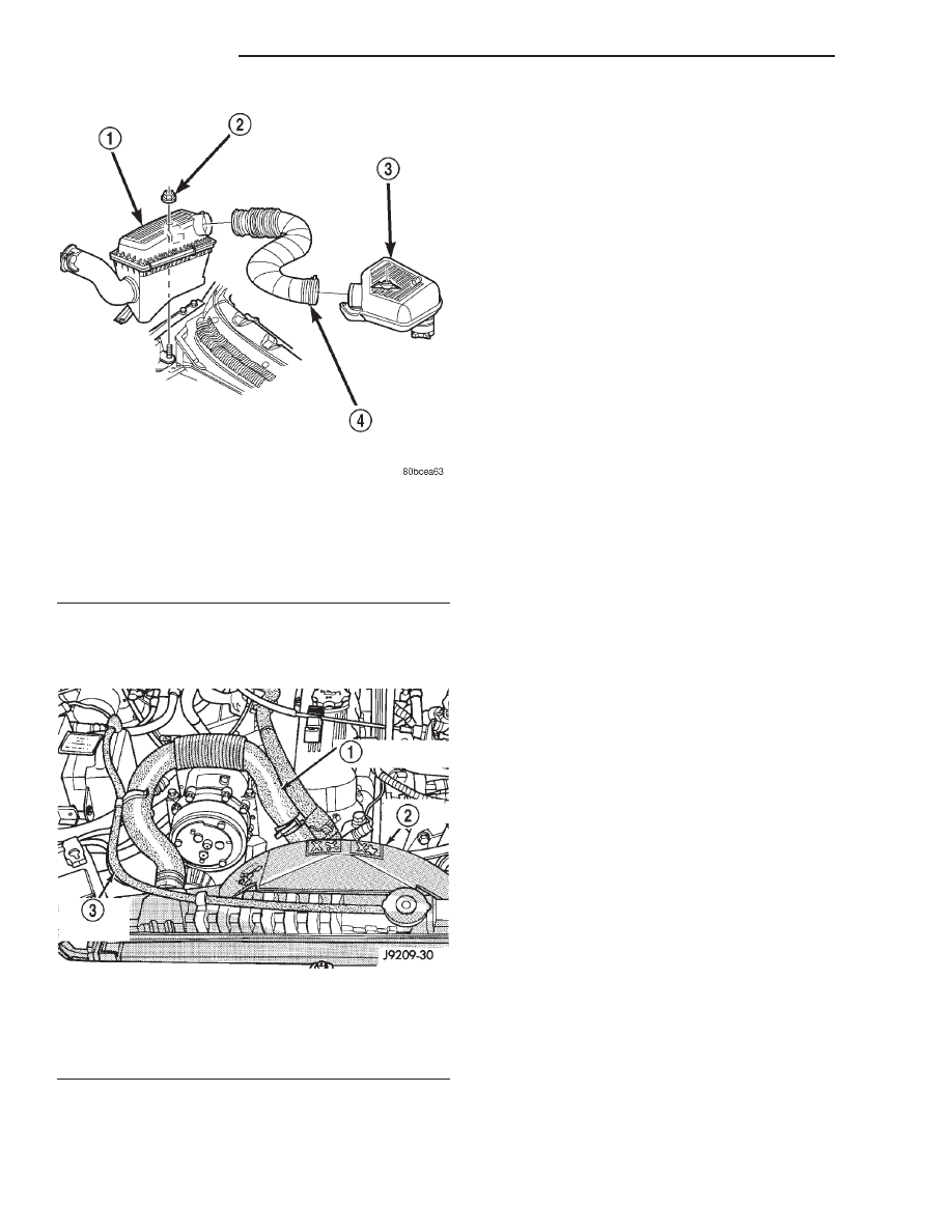
Fig. 47 Air Cleaner and Resonator Removal and

Installation

1 – AIR CLEANER ASSEMBLY
2 – NUT AND WASHER
3 – RESONATOR ASSEMBLY
4 – AIR INLET HOSE

Fig. 48 Upper Radiator Hose, Coolant Recovery

Hose & Fan Shroud

1 – UPPER RADIATOR HOSE
2 – FAN SHROUD
3 – COOLANT RECOVERY HOSE

9 - 32

2.5L ENGINE

XJ

REMOVAL AND INSTALLATION (Continued)

(32) Raise the engine slightly off the front sup-

ports.

(33) Place a support stand under the converter or

flywheel housing.

(34) Lift the engine out of the engine compartment

and install on an engine stand.

(35) Install the oil filter to keep foreign material

out of the engine.

INSTALLATION

(1) Remove the oil filter.
(2) Lift the engine off the stand and lower it into

the engine compartment. For easier installation, it
may be useful to remove the engine support cushions
from the engine support brackets as an aide for
alignment of the engine-to-transmission.

(3) Insert the transmission shaft into the clutch

spline. (M/T models)

(4) Align the flywheel housing with the engine.
(5) Install and tighten the flywheel housing lower

bolts.

(6) Install

the

engine

support

cushions

(if

removed).

(7) Lower the engine and engine support cushions

onto the engine compartment brackets.

(8) Remove the engine lifting device.
(9) Raise the vehicle.
(10) Install the converter-housing access cover.
(11) Install the exhaust pipe support.
(12) Install the starter motor and connect the

cable. Tighten the bolts to 45 N·m (33 ft. lbs.) torque.

(13) Tighten the engine support cushion through-

bolt nuts.

(14) Connect the exhaust pipe to the manifold.
(15) Install the oil filter.
(16) Lower the vehicle.
(17) Connect the coolant hoses and tighten the

clamps.

(18) If equipped with power steering:

(a) Remove the protective caps
(b) Connect the hoses to the fittings at the steer-

ing gear. Tighten the nut to 52 N·m (38 ft. lbs.)
torque.

(c) Fill the pump reservoir with fluid.

(19) Remove

the

pulley-to-water

pump

flange

alignment capscrew and install the fan assembly.

(20) Install the fan shroud and radiator and con-

denser (if equipped with air conditioning).

(21) Connect the radiator hoses.
(22) Connect the oxygen sensor wire connector.
(23) Connect the throttle cable and install the rod.

Connect the transmission and speed control cables (if
equipped)

(24) Connect the fuel supply line to the injector

rail. push until a “click” is heard. Re-install latch
clip.

(25) Connect all the vacuum hoses and wire con-

nectors.

(26) Connect suction/discharge hose to compressor.

(if equipped)

(27) Fill the power steering reservoir.
(28) Connect the battery cables.
(29) Install the air cleaner (Fig. 47).
(30) Install the hood.
(31) Add engine oil and coolant.
(32) Start the engine and inspect for leaks.
(33) Stop the engine and check the fluid levels.

Add fluid, as required.

(34) Recharge air conditioning (Refer to group 24,

Heating and Air Conditioning for proper procedures).

INTAKE MANIFOLD

REMOVAL

(1) Disconnect the battery negative cable.
(2) Remove the air inlet hose and resonator from

the throttle body and air cleaner (Fig. 49).

(3) Loosen the accessory drive belt tension and

remove the belt from the power steering pump (refer
to Group 07, Cooling Systems for proper procedures).

(4) Remove the power steering pump and brackets

from the water pump and intake manifold. Secure
power steering pump and bracket out of the way.

Fig. 49 Air Cleaner, Resonator and air Inlet Hose

Removal and Installation

1 – AIR CLEANER ASSEMBLY
2 – NUT AND WASHER
3 – RESONATOR ASSEMBLY
4 – AIR INLET HOSE

XJ

2.5L ENGINE

9 - 33

REMOVAL AND INSTALLATION (Continued)

(5) Perform fuel system pressure release procedure

(refer to Group 14, Fuel System for correct proce-
dure).

(6) Disconnect fuel supply tube from the fuel rail.

Some fuel lines require a special tool for removal/in-
stallation (refer to Group 14, Fuel System - Quick
Connect Fittings).

(7) Disconnect the accelerator cable, the cruise

control cable (if equipped), and the transmission line
pressure cable (if equipped) from the throttle body
and remove them from the cable bracket.

CAUTION: When disconnecting the cruise control
connector at the throttle body, DO NOT pry the con-
nector off with pliers or screwdriver. Use finger
pressure only. Prying the connector off could break
it.

(8) Disconnect the electrical connectors. Pull the

harnesses away from the manifold and secure them
so they do not interfere with the manifold removal
and installation process.

• The throttle position sensor.

• The idle air control motor.

• The coolant temperature sensor at the thermo-

stat.

• The manifold air temperature sensor at the

intake manifold.

• The fuel injectors.

• The oxygen sensor.
(9) Disconnect the crankcase ventilation (CCV)

vacuum hose and manifold absolute pressure (MAP)
sensor vacuum hose connector at the intake mani-
fold.

(10) Disconnect vacuum hose from vacuum port on

the intake manifold.

(11) Disconnect CCV hose at the cylinder head

cover (Fig. 50).

(12) Remove the molded vacuum harness.
(13) Disconnect the vacuum brake booster hose at

the intake manifold.

(14) Remove bolts 2 through 5 securing the intake

manifold to the cylinder head (Fig. 51). Slightly
loosen bolt No.1 and nuts 6 and 7.

(15) Remove the intake manifold and gaskets.

Drain the coolant from the manifold.

INSTALLATION

(1) Clean the intake manifold and cylinder head

mating surfaces. DO NOT allow foreign material
to enter either the intake manifold or the ports
in the cylinder head.

(2) Install the new intake manifold gasket over the

locating dowels.

(3) Position the manifold in place and finger

tighten the mounting bolts.

(4) Tighten the fasteners in sequence and to the

specified torque (Fig. 51).

• Fastener No.1—Tighten to 41 N·m (30 ft. lbs.)

torque.

• Fasteners Nos.2 through 5—Tighten to 31 N·m

(23 ft. lbs.) torque.

• Fasteners Nos.6 and 7—Tighten to 23 N·m (17

ft. lbs.) torque.

(5) Connect fuel supply tube to the fuel rail inlet.

Push tube until a “click” is heard. Before connect-
ing the fuel line to the fuel rail replace the
O-rings at the quick-connect fuel line coupling.

(6) Pull out on the fuel supply tube to ensure that

it is locked in place.

(7) Connect the molded vacuum hoses to the vac-

uum port on the intake manifold and the cylinder
head cover.

(8) Connect the electrical connectors.
• The throttle position sensor.

• The idle air control motor.

• The coolant temperature sensor at the thermo-

stat housing.

• The fuel injectors.

• The air manifold temperature sensor.

• The oxygen sensor.
(9) Connect the CCV vacuum hose and MAP sen-

sor vacuum hose connectors to the throttle body.

Fig. 50 Crankcase Ventilation (CCV) Hose—2.5L

Engine

1 – AIR INLET FITTING
2 – AIR FILTER COVER
3 – FIXED ORIFICE FITTING

9 - 34

2.5L ENGINE

XJ

REMOVAL AND INSTALLATION (Continued)

(10) Install the power steering pump and bracket

assembly to the water pump and intake manifold.
Hand start the three (3) tensioner bracket to p/s
pump to intake manifold bolts and the two (2) ten-
sioner bracket to water pump bolts.

(11) Tighten the power steering pump bolts to 28

N·m (21 ft. lbs.) Tighten the tensioner bracket to
water pump bolts to 28 N·m (21 ft. lbs.).

(12) Connect the accelerator cable, cruise control

cable (if equipped), and the transmission line pres-
sure cable (if equipped) to the hold-down bracket and
the throttle lever.

(13) Install and tension the accessory drive belt.

Refer to Group 7, Cooling System for the proper pro-
cedure.

CAUTION: Ensure that the accessory drive belt is
routed correctly. Failure to do so can cause the
water pump to turn in the opposite direction result-
ing in engine overheating. Refer to Group 7, Cool-
ing System for the proper procedure.

(14) Connect the air inlet hose and resonator to

the throttle body and the air cleaner.

(15) Connect the battery negative cable.
(16) Start the engine and check for leaks.

EXHAUST MANIFOLD

REMOVAL

(1) Disconnect the battery negative cable.
(2) Raise the vehicle.
(3) Disconnect the exhaust pipe from the engine

exhaust manifold.

(4) Lower the vehicle.
(5) Remove intake manifold (refer to procedure in

this section)

(6) Remove fasteners 2 through 5 and remove the

intake manifold (Fig. 51).

(7) Remove fasteners 1, 6 and 7 and remove the

engine exhaust manifold (Fig. 51).

INSTALLATION

(1) Clean the intake and engine exhaust manifolds

and cylinder head mating surfaces. DO NOT allow
foreign material to enter either the intake man-
ifold or the ports in the cylinder head.

(2) Install a new intake manifold gasket over the

alignment dowels on the cylinder head.

(3) Install the engine exhaust manifold assembly.

Exhaust manifold must be centrally located
over the end studs and spacer (Fig. 51).

(4) Tighten bolt No.1 to 41 N·m (30 ft. lbs.) torque

(Fig. 51).

(5) Install the intake manifold on the cylinder

head dowels (Fig. 51).

(6) Install bolts 2 through 5 (Fig. 51). Tighten

these bolts to 31 N·m (23 ft. lbs.) torque.

(7) Install new engine exhaust manifold spacers

over the engine exhaust manifold mounting studs in
the cylinder head (Fig. 51).

(8) Tighten nuts 6 and 7 to 23 N·m (17 ft. lbs.)

torque (Fig. 51).

(9) Install all components to the intake manifold.
(10) Raise the vehicle.
(11) Connect the exhaust pipe to the engine

exhaust manifold. Tighten the bolts to 31 N·m (23 ft.
lbs.) torque.

(12) Lower the vehicle.
(13) Connect the battery negative cable.
(14) Start the engine and check for leaks.

CYLINDER HEAD COVER

A cured gasket is part of the engine cylinder head

cover.

REMOVAL

(1) Disconnect negative cable from battery.
(2) Disconnect the Crankcase Ventilation (CCV)

vacuum hose from engine cylinder head cover (Fig.
52).

(3) Remove the air inlet hose and resonator from

the air cleaner and throttle body.

(4) Remove the engine cylinder head cover mount-

ing bolts.

(5) Remove the engine cylinder head cover (Fig.

52).

(6) Remove any original sealer from the cover seal-

ing surface of the engine cylinder head and clean the
surface using a fabric cleaner.

(7) Remove all residue from the sealing surface

using a clean, dry cloth.

Fig. 51 Intake/Exhaust Manifold Removal/

Installation—2.5L Engine

XJ

2.5L ENGINE

9 - 35

REMOVAL AND INSTALLATION (Continued)


Content   ..  289  290  291  292   ..