Jeep XJ. Manual - part 138


  Index      Jeep     Jeep XJ - service repair manual 2001 year


Search            


Content   ..  136  137  138  139   ..


Jeep XJ. Manual - part 138


SEAT HEAT INTERFACE MODULE

Before testing the seat heat interface module, test

the heated seat switch, the heated seat elements, and
the heated seat sensor as described in the Diagnosis
and Testing section of this group. If testing of the
heated seat switch, elements, and sensor reveals no
problems, proceed as follows. For circuit descriptions
and diagrams, refer to 8W - 63 - Power Seat With
Heated Seats in Group 8W - Wiring Diagrams.

(1) Replace the seat heat interface module with a

known good unit and test the operation of the heated
seats. If OK, discard the faulty seat heat interface
module. If not OK, go to Step 2.

(2) Test each of the circuits from the heated seat

switch, heated seat relay, heated seat elements, and
heated seat sensor to the seat heat interface module.
Repair any short or open circuits as required.

REMOVAL AND INSTALLATION

HEATED SEAT SWITCH

WARNING: ON VEHICLES EQUIPPED WITH AIR-
BAGS,

REFER

TO

GROUP

8M

-

PASSIVE

RESTRAINT SYSTEMS BEFORE ATTEMPTING ANY
STEERING

WHEEL,

STEERING

COLUMN,

OR

INSTRUMENT PANEL COMPONENT DIAGNOSIS OR
SERVICE. FAILURE TO TAKE THE PROPER PRE-
CAUTIONS COULD RESULT IN ACCIDENTAL AIR-
BAG DEPLOYMENT AND POSSIBLE PERSONAL
INJURY.

(1) Disconnect and isolate the battery negative

cable.

(2) Using a trim stick or another suitable wide

flat-bladed tool, gently pry around the perimeter
edges of the heated switch assembly bezel to release
the assembly from the console. Remove the assembly
from the console.

(3) Pull the switch assembly out from the console

far enough to access and unplug the wire harness
connectors.

(4) Remove the heated seat switch assembly from

the console.

(5) Remove the heated seat switch(es) from the

heated seat switch assembly.

(6) Reverse the removal procedures to install.

SEAT HEAT INTERFACE MODULE

(1) Move the right power seat adjuster to its full

up and full rear stop positions.

(2) Disconnect and isolate the battery negative

cable.

(3) Unhook the seat cushion cover retainer from

the seat cushion frame and pull back the seat cush-
ion cover.

(4) Pull back the seat cushion to allow access to

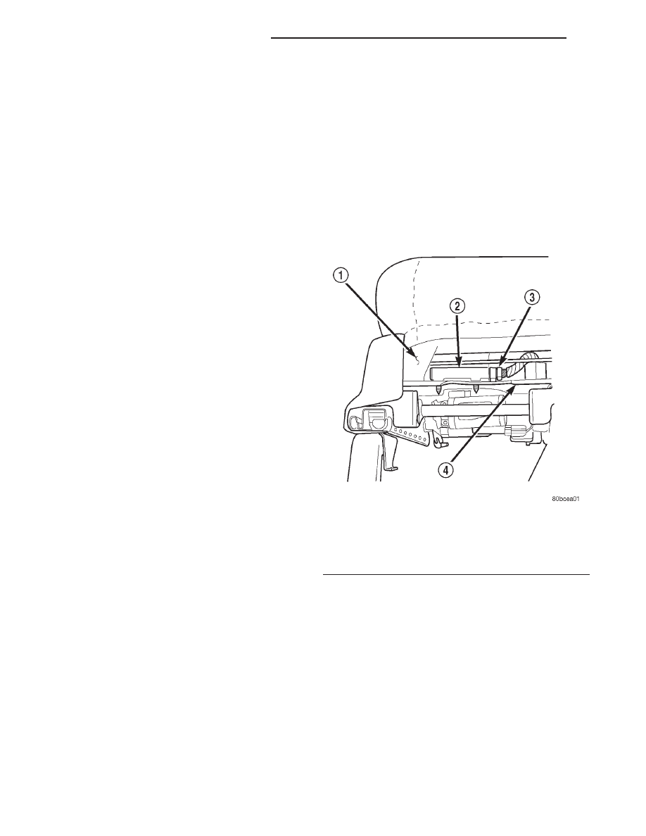
the Seat Heat Interface Module (SHIM).

(5) Pull the SHIM upward to release the two

mounting fasteners from either the module or the
mounting bracket. Unplug the wire harness connec-
tor from the module (Fig. 2).

WARNING: THERE

ARE

MANY

SHARP

METAL

EDGES ON THE SEAT CUSHION FRAME AND SEAT
ADJUSTER RAILS UNDER THE SEAT. WHEN PER-
FORMING THIS SERVICE, A LONG-SLEEVED SHIRT
AND GLOVES SHOULD BE WORN IN ORDER TO
AVOID UNNECESSARY CUTS AND ABRASIONS TO
EXPOSED SKIN.

(6) Reverse the removal procedures to install. Be

certain that the SHIM terminals are aligned with the
cavities in the wire harness connector before pushing
the module firmly into place.

HEATED SEAT RELAY

(1) Move the right power seat adjuster to its full

up and full rear stop positions.

(2) Disconnect and isolate the battery negative

cable.

(3) Unhook the seat cushion cover retainer from

the seat cushion frame and pull back the seat cush-
ion cover.

(4) Pull back the seat cushion to allow access to

the Heated Seat Relay.

Fig. 2 Seat Heat Interface Module Remove/Install

1 – SEAT CUSHION FRAME
2 – SEAT HEAT INTERFACE MODULE
3 – WIRE HARNESS CONNECTOR
4 – POWER SEAT TRACK FRONT BRACKET

8N - 12

ELECTRICALLY HEATED SYSTEMS

XJ

DIAGNOSIS AND TESTING (Continued)

(5) Cut the Christmas tree fastener to remove the

Heated Seat Relay fastener from the mounting
bracket. Unplug the wire harness connector from the
relay (Fig. 3).

(6) Reverse the removal procedures to install. A

new Christmas tree fastener must be used to mount
the relay. Be certain that the relay terminals are
aligned with the cavities in the wire harness connec-
tor before pushing the relay firmly into place.

Fig. 3 Heated Seat Relay Remove/Install

1 – HEATED SEAT RELAY
2 – SEAT CUSHION FRAME
3 – WIRE HARNESS CONNECTOR
4 – POWER SEAT TRACK FRONT BRACKET

XJ

ELECTRICALLY HEATED SYSTEMS

8N - 13

REMOVAL AND INSTALLATION (Continued)

POWER DISTRIBUTION SYSTEMS

TABLE OF CONTENTS

page

page

DESCRIPTION AND OPERATION

POWER DISTRIBUTION SYSTEM. . . . . . . . . . . . . 1
POWER DISTRIBUTION CENTER . . . . . . . . . . . . . 2
IGNITION-OFF DRAW FUSE . . . . . . . . . . . . . . . . . 2
JUNCTION BLOCK . . . . . . . . . . . . . . . . . . . . . . . . 3

REMOVAL AND INSTALLATION

POWER DISTRIBUTION CENTER . . . . . . . . . . . . . 4

IGNITION-OFF DRAW FUSE . . . . . . . . . . . . . . . . . 5
JUNCTION BLOCK . . . . . . . . . . . . . . . . . . . . . . . . 6

DISASSEMBLY AND ASSEMBLY

POWER DISTRIBUTION CENTER . . . . . . . . . . . . . 7

SPECIAL TOOLS

POWER DISTRIBUTION SYSTEMS . . . . . . . . . . 10

DESCRIPTION AND OPERATION

POWER DISTRIBUTION SYSTEM

DESCRIPTION

This

group

covers

the

various

standard

and

optional power distribution components used on this
model. The power distribution system for this vehicle
consists of the following components:

• Power Distribution Center (PDC)

• Junction Block (JB).
The power distribution system also incorporates

various types of circuit control and protection fea-
tures, including:

• Automatic resetting circuit breakers

• Blade-type fuses

• Maxi fuse-type fusible links

• Relays.
Following are general descriptions of the major

components in the power distribution system. See the
owner’s manual in the vehicle glove box for more
information on the features and use of all of the
power distribution system components. Refer to the
index in this service manual for the location of com-
plete circuit diagrams for the various power distribu-
tion system components.

NOTE: This group covers both Left-Hand Drive
(LHD) and Right-Hand Drive (RHD) versions of this
model. Whenever required and feasible, the RHD
versions of affected vehicle components have been
constructed as mirror-image of the LHD versions.
While most of the illustrations used in this group
represent only the LHD version, the diagnostic and
service

procedures

outlined

can

generally

be

applied to either version. Exceptions to this rule
have been clearly identified as LHD or RHD, if a
special illustration or procedure is required.

OPERATION

The power distribution system for this vehicle is

designed to provide safe, reliable, and centralized dis-
tribution points for the electrical current required to
operate all of the many standard and optional facto-
ry-installed

electrical

and

electronic

powertrain,

chassis, safety, security, comfort and convenience sys-
tems. At the same time, the power distribution sys-
tem was designed to provide ready access to these
electrical distribution points for the vehicle techni-
cian to use when conducting diagnosis and repair of
faulty circuits. The power distribution system can
also prove useful for the sourcing of additional elec-
trical circuits that may be required to provide the
electrical current needed to operate many accessories
that the vehicle owner may choose to have installed
in the aftermarket.

XJ

POWER DISTRIBUTION SYSTEMS

8O - 1


Content   ..  136  137  138  139   ..