Jeep XJ. Manual - part 118


  Index      Jeep     Jeep XJ - service repair manual 2001 year


Search            


Content   ..  116  117  118  119   ..


Jeep XJ. Manual - part 118


(2) Remove the wiper arms from the wiper pivots.

See Wiper Arm in this group for the procedures.

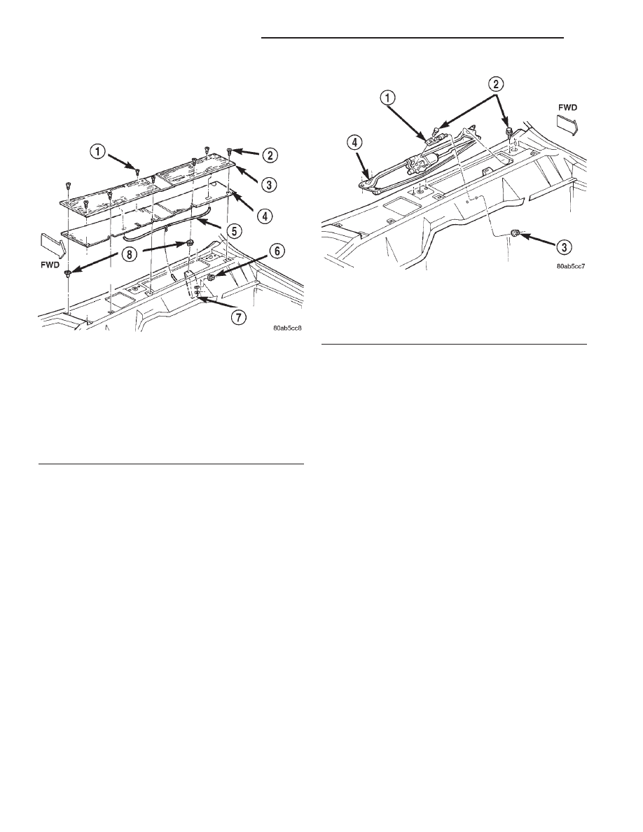
(3) Remove the eight screws that secure the cowl

plenum cover/grille panel and screen to the cowl top
panel (Fig. 9).

(4) Carefully lift the cowl plenum cover/grille panel

and screen from the vehicle far enough to access the
windshield washer plumbing. Use care so as not to
damage the paint around the pivot openings of the
panel.

(5) Disconnect the windshield washer supply hose

and the passenger side washer nozzle hose from the
washer nozzle supply hose tee fitting.

(6) Remove the cowl plenum cover/grille panel and

screen from the vehicle.

(7) Reach into the cowl plenum and unplug the

wiper motor wire harness connector.

(8) Open and support the hood
(9) Remove the two nuts that secure the studs of

the wiper module mounting bracket and reinforce-
ment to the dash panel (Fig. 10).

(10) Remove the four screws near the wiper pivots

that secure the wiper module to the cowl plenum
panel.

(11) Remove the wiper module from the cowl ple-

num as a unit.

(12) Reverse the removal procedures to install.

Tighten the mounting hardware as follows:

• Wiper module mounting screws - 6 N·m (50 in.

lbs.)

• Wiper module mounting bracket and reinforce-

ment nuts - 6 N·m (50 in. lbs.).

REAR

(1) Disconnect and isolate the battery negative

cable.

(2) From the outside of the liftgate glass, remove

the rear wiper arm from the rear wiper motor output
shaft. See Wiper Arm in this group for the proce-
dures.

(3) From the outside of the liftgate, remove the

rear wiper motor output shaft nut (Fig. 11).

(4) Pull the rear wiper motor output shaft bezel

and rubber gasket away from the liftgate far enough
to access the washer supply hose.

(5) Disconnect the washer supply hose from the

internal nipple on the bezel.

(6) Remove the bezel and rubber gasket from the

motor output shaft.

(7) Remove the liftgate trim panel from the lift-

gate. Refer to Group 23 - Body for the procedures.

(8) Unplug the rear wiper motor wire harness con-

nector.

(9) Remove the two screws that secure the rear

wiper motor mounting bracket to the liftgate inner
panel.

(10) Remove the rear wiper motor and mounting

bracket from the liftgate as a unit.

(11) Reverse the removal procedures to install.

Tighten the mounting hardware as follows:

• Rear wiper motor mounting bracket screws - 5

N·m (45 in. lbs.)

Fig. 9 Cowl Plenum Cover/Grille Panel Remove/

Install

1 – SCREW
2 – SCREW
3 – GRILLE PANEL
4 – SCREEN
5 – WASHER HOSE
6 – NUT
7 – BRACKET
8 – NUT

Fig. 10 Wiper Linkage Module Remove/Install

1 – BRACKET AND GROMMET
2 – SCREW
3 – NUT
4 – LINKAGE AND PIVOT MODULE

8K - 10

WIPER AND WASHER SYSTEMS

XJ

REMOVAL AND INSTALLATION (Continued)

• Rear wiper motor output shaft retaining nut - 3

N·m (27 in. lbs.).

WIPER SWITCH AND WASHER SWITCH

FRONT

WARNING: ON VEHICLES EQUIPPED WITH AIR-
BAGS,

REFER

TO

GROUP

8M

-

PASSIVE

RESTRAINT SYSTEMS BEFORE ATTEMPTING ANY
STEERING

WHEEL,

STEERING

COLUMN,

OR

INSTRUMENT PANEL COMPONENT DIAGNOSIS OR
SERVICE. FAILURE TO TAKE THE PROPER PRE-
CAUTIONS COULD RESULT IN ACCIDENTAL AIR-
BAG DEPLOYMENT AND POSSIBLE PERSONAL
INJURY.

(1) Disconnect and isolate the battery negative

cable.

(2) Remove the knee blocker from the instrument

panel. See Knee Blocker in Group 8E - Instrument
Panel Systems for the procedures.

(3) Remove the three screws that secure the lower

steering column shroud to the upper shroud (Fig. 12).

(4) If the vehicle is equipped with a standard non-

tilt steering column, loosen the two upper steering
column mounting nuts. If the vehicle is equipped
with the optional tilt steering column, move the tilt
steering column to the fully lowered position.

(5) Remove both the upper and lower shrouds from

the steering column.

(6) Remove the two screws that secure the switch

water shield and bracket to the top of the steering
column (Fig. 13).

(7) Remove the one screw located below the multi-

function switch lever that secures the switch water
shield and bracket to the steering column (Fig. 14).

(8) Gently pull the lower mounting tab of the

switch water shield bracket away from the steering
column far enough to clear the screw boss below the
multi-function switch lever.

(9) Lift the water shield and bracket with the

multi-function switch off of the left side of the steer-
ing column as a unit and move it out of the way. If
the vehicle is equipped with the optional tilt steering
column, lifting gently upward on the tilt release lever

Fig. 11 Rear Wiper Motor Remove/Install

1 – LIFTGATE
2 – ARM
3 – NUT
4 – NUT
5 – SCREW
6 – MOTOR AND BRACKET
7 – BLADE
8 – BEZEL
9 – CLIP
10 – HOSE

Fig. 12 Steering Column Shrouds Remove/Install

1 – UPPER SHROUD
2 – SCREW (3)
3 – LOWER SHROUD
4 – STEERING WHEEL

XJ

WIPER AND WASHER SYSTEMS

8K - 11

REMOVAL AND INSTALLATION (Continued)

will provide additional clearance to ease multi-func-
tion switch removal.

(10) Gently pull the windshield wiper and washer

switch up and away from the right side of the steer-
ing column far enough to access the wire harness
connector.

(11) Unplug the wire harness connector from the

windshield wiper and washer switch.

(12) Remove the windshield wiper and washer

switch from the steering column.

(13) Reverse the removal procedures to install.

Tighten the upper switch mounting screws to 2.2
N·m (20 in. lbs.). Tighten the lower switch water
shield and bracket screw to 1.1 N·m (10 in. lbs.).
Tighten the non-tilt steering column mounting nuts
to 22 N·m (200 in. lbs.) and the steering column
shroud mounting screws to 2 N·m (18 in. lbs.).

REAR

WARNING: ON VEHICLES EQUIPPED WITH AIR-
BAGS,

REFER

TO

GROUP

8M

-

PASSIVE

RESTRAINT SYSTEMS BEFORE ATTEMPTING ANY
STEERING

WHEEL,

STEERING

COLUMN,

OR

INSTRUMENT PANEL COMPONENT DIAGNOSIS OR
SERVICE. FAILURE TO TAKE THE PROPER PRE-
CAUTIONS COULD RESULT IN ACCIDENTAL AIR-
BAG DEPLOYMENT AND POSSIBLE PERSONAL
INJURY.

(1) Disconnect and isolate the battery negative

cable.

(2) Remove the center bezel from the instrument

panel. See Instrument Panel Center Bezel in Group
8E - Instrument Panel Systems for the procedures.

(3) Remove the three screws that secure the acces-

sory switch bezel to the instrument panel (Fig. 15).

(4) Pull the accessory switch bezel out from the

instrument panel far enough to access the wire har-
ness connectors.

(5) Unplug the wire harness connectors from the

rear of the accessory switches, the cigar lighter and
the power outlet.

(6) Remove the accessory switch bezel from the

instrument panel.

(7) With a small thin-bladed screwdriver, gently

pry the snap clips at the top and bottom of the rear

Fig. 13 Water Shield Upper Screws Remove/Install

1 – MOUNTING SCREWS
2 – HAZARD WARNING SWITCH KNOB
3 – MULTI-FUNCTION SWITCH LEVER
4 – WATER SHIELD AND BRACKET
5 – WIPER SWITCH LEVER

Fig. 14 Water Shield Lower Screw Remove/Install

1 – MULTI-FUNCTION SWITCH LEVER
2 – WATER SHIELD AND BRACKET
3 – LOWER MOUNTING SCREW
4 – LOWER MOUNTING TAB

Fig. 15 Accessory Switch Bezel Remove/Install

1 – ACCESSORY SWITCH BEZEL
2 – SCREW

8K - 12

WIPER AND WASHER SYSTEMS

XJ

REMOVAL AND INSTALLATION (Continued)

wiper and washer switch receptacle on the back of
the accessory switch bezel and pull the switch out of
the bezel.

(8) Reverse the removal procedures to install. Be

certain that both of the switch snap clip retainers in
the receptacle on the back of the accessory switch
bezel are fully engaged. Tighten the mounting screws
to 2.2 N·m (20 in. lbs.).

WASHER SYSTEM

WASHER RESERVOIR

(1) Disconnect and isolate the battery negative

cable.

(2) The washer reservoir filler neck is held in the

reservoir by an interference fit. Remove the filler
neck from the reservoir using a combination of pull-
ing, rocking and twisting actions (Fig. 16).

(3) Remove the engine air filter housing. Refer to

Group 14 - Fuel System for the procedures.

(4) Remove the two screws that secure the washer

reservoir to the inner fender shield (Fig. 17).

(5) Raise and support the vehicle.
(6) Remove the left front inner wheelhouse splash

shield. Refer to Group 23 - Body for the procedures.

(7) Remove the washer supply hose(s) from the

washer pump(s) and drain the washer fluid from the
reservoir into a clean container for reuse.

(8) Unplug the wire harness connectors from the

washer pump(s) and the washer fluid level sensor.

(9) Slide the reservoir slightly towards the rear of

the vehicle to release the two hooks from the inner
fender ledge slots.

(10) Lower the front of the washer reservoir and

slide the unit forward to remove it from the vehicle.

(11) Reverse the removal procedures to install.

Tighten the reservoir mounting screws to 3 N·m (26
in. lbs.).

WASHER PUMP

(1) Disconnect and isolate the battery negative

cable.

(2) Raise and support the vehicle.
(3) Remove the left front inner wheelhouse splash

shield. Refer to Group 23 - Body for the procedures.

(4) Remove the washer supply hose(s) from the

barbed outlet nipple of the washer pump(s) and drain
the washer fluid from the reservoir into a clean con-
tainer for reuse.

(5) Unplug the wire harness connectors from the

washer pump(s).

(6) Using a trim stick or another suitable wide

flat-bladed tool, gently pry the barbed inlet nipple of
the washer pump out of the rubber grommet seal in
the reservoir. Care must be taken not to damage the
reservoir.

(7) Remove the rubber grommet seal from the res-

ervoir and discard.

Fig. 16 Washer Reservoir Filler Neck Remove/Install

1 – RESERVOIR
2 – LEFT FENDER
3 – FILLER NECK AND CAP

Fig. 17 Washer Reservoir Remove/Install

1 – SCREW
2 – FENDER
3 – WASHER RESERVOIR
4 – FILLER NECK
5 – SCREW
6 – FLUID LEVEL SENSOR
7 – REAR WASHER PUMP
8 – FRONT WASHER PUMP
9 – HOOK

XJ

WIPER AND WASHER SYSTEMS

8K - 13

REMOVAL AND INSTALLATION (Continued)


Content   ..  116  117  118  119   ..