Jeep XJ. Manual - part 110


  Index      Jeep     Jeep XJ - service repair manual 2001 year


Search            


Content   ..  108  109  110  111   ..


Jeep XJ. Manual - part 110


OPERATION

Within the two halves of the molded plastic horn

housing are a flexible diaphragm, a plunger, an elec-
tromagnetic coil and a set of contact points. The dia-
phragm

is

secured

in

suspension

around

its

perimeter by the mating surfaces of the horn hous-
ing. The plunger is secured to the center of the dia-
phragm

and

extends

into

the

center

of

the

electromagnet. The contact points control the current
flow through the electromagnet.

When the horn is energized, electrical current

flows through the closed contact points to the electro-
magnet. The resulting electromagnetic field draws
the plunger and diaphragm toward it until that
movement mechanically opens the contact points.
When the contact points open, the electromagnetic
field collapses allowing the plunger and diaphragm to
return to their relaxed positions and closing the con-
tact points again. This cycle continues repeating at a
very rapid rate producing the vibration and move-
ment of air that creates the sound that is directed
through the horn outlet.

HORN RELAY

DESCRIPTION

The horn relay is a electromechanical device that

switches battery current to the horn when the horn
switch grounds the relay coil. The horn relay is
located in the junction block on the right cowl side
inner panel below the instrument panel in the pas-
senger compartment. If a problem is encountered
with a continuously sounding horn, it can usually be
quickly resolved by removing the horn relay from the
junction block until further diagnosis is completed.
Refer to Junction Block in the Contents of Group
8W - Wiring Diagrams for horn relay identification
and location.

The horn relay is a International Standards Orga-

nization (ISO) relay. Relays conforming to the ISO
specifications have common physical dimensions, cur-
rent capacities, terminal patterns, and terminal func-
tions.

The horn relay cannot be repaired or adjusted and,

if faulty or damaged, it must be replaced.

OPERATION

The ISO relay consists of an electromagnetic coil, a

resistor or diode, and three (two fixed and one mov-
able) electrical contacts. The movable (common feed)
relay contact is held against one of the fixed contacts
(normally closed) by spring pressure. When the elec-
tromagnetic coil is energized, it draws the movable
contact away from the normally closed fixed contact,
and holds it against the other (normally open) fixed
contact.

When the electromagnetic coil is de-energized,

spring pressure returns the movable contact to the
normally closed position. The resistor or diode is con-
nected in parallel with the electromagnetic coil in the
relay, and helps to dissipate voltage spikes that are
produced when the coil is de-energized.

HORN SWITCH

DESCRIPTION

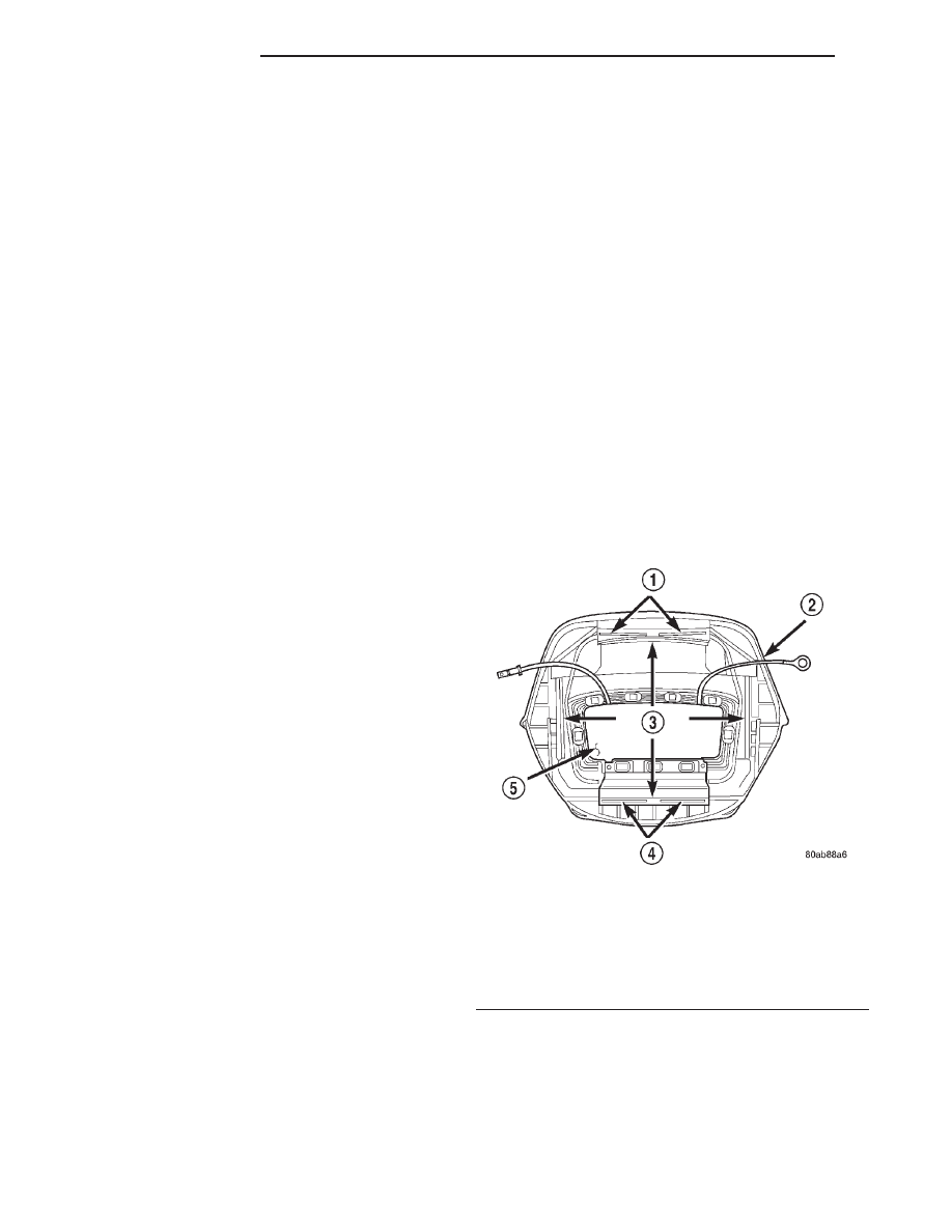
A center-blow, normally open, resistive membrane-

type horn switch is secured with heat stakes to the
back side of the driver side airbag module trim cover
in the center of the steering wheel (Fig. 1). The
switch consists of two plastic membranes, one that is
flat and one that is slightly convex. These two mem-
branes are secured to each other around the perime-
ter. Inside the switch, the centers of the facing
surfaces of these membranes each has a grid made
with an electrically conductive material applied to it.
One of the grids is connected to a circuit that pro-
vides it with continuity to ground at all times. The
grid of the other membrane is connected to the horn
relay control circuit.

The steering wheel and steering column must be

properly grounded in order for the horn switch to
function properly. The horn switch is only serviced as
a part of the driver side airbag module trim cover. If
the horn switch is damaged or faulty, or if the driver
side airbag is deployed, the driver side airbag module

Fig. 1 Driver Side Airbag Module Trim Cover and

Horn Switch

1 – RETAINER SLOTS
2 – TRIM COVER
3 – LOCKING BLOCKS
4 – RETAINER SLOTS
5 – HORN SWITCH

8G - 2

HORN SYSTEMS

XJ

DESCRIPTION AND OPERATION (Continued)

trim cover and horn switch must be replaced as a
unit.

OPERATION

When the center area of the driver side airbag trim

cover is depressed, the electrically conductive grids
on the facing surfaces of the horn switch membranes
contact each other, closing the switch circuit. The
completed horn switch circuit provides a ground for
the control coil side of the horn relay, which activates
the relay. When the horn switch is released, the
resistive tension of the convex membrane separates
the two electrically conductive grids and opens the
switch circuit.

DIAGNOSIS AND TESTING

HORN RELAY

The horn relay (Fig. 2) is located in the junction

block on the right cowl side inner panel below the
instrument panel in the passenger compartment. If a
problem is encountered with a continuously sounding
horn, it can usually be quickly resolved by removing
the horn relay from the junction block until further
diagnosis is completed. Refer to Junction Block in
the Contents of Group 8W - Wiring Diagrams for
horn relay identification and location. For complete
circuit diagrams, refer to Horn/Cigar Lighter in the
Contents of Group 8W - Wiring Diagrams.

WARNING: ON VEHICLES EQUIPPED WITH AIR-
BAGS,

REFER

TO

GROUP

8M

-

PASSIVE

RESTRAINT SYSTEMS BEFORE ATTEMPTING ANY
STEERING

WHEEL,

STEERING

COLUMN,

OR

INSTRUMENT PANEL COMPONENT DIAGNOSIS OR
SERVICE. FAILURE TO TAKE THE PROPER PRE-
CAUTIONS COULD RESULT IN ACCIDENTAL AIR-
BAG DEPLOYMENT AND POSSIBLE PERSONAL
INJURY.

(1) Remove the horn relay from the junction block.

Refer to Horn Relay in the Removal and Installa-
tion section of this group for the procedures.

(2) A relay in the de-energized position should

have continuity between terminals 87A and 30, and
no continuity between terminals 87 and 30. If OK, go
to Step 3. If not OK, replace the faulty relay.

(3) Resistance between terminals 85 and 86 (elec-

tromagnet) should be 75

6 5 ohms. If OK, go to Step

4. If not OK, replace the faulty relay.

(4) Connect a battery to terminals 85 and 86.

There should now be continuity between terminals
30 and 87, and no continuity between terminals 87A
and 30. If OK, perform the Relay Circuit Test that
follows. If not OK, replace the faulty relay.

RELAY CIRCUIT TEST

(1) The relay common feed terminal cavity (30) is

connected to battery voltage and should be hot at all
times. If OK, go to Step 2. If not OK, repair the open
circuit to the fuse in the junction block as required.

(2) The relay normally closed terminal (87A) is

connected to terminal 30 in the de-energized position,
but is not used for this application. Go to Step 3.

(3) The relay normally open terminal (87) is con-

nected to the common feed terminal (30) in the ener-
gized position. This terminal supplies battery voltage
to the horn(s). There should be continuity between
the cavity for relay terminal 87 and the horn relay
output circuit cavity of each horn wire harness con-
nector at all times. If OK, go to Step 4. If not OK,
repair the open circuit to the horn(s) as required.

(4) The coil battery terminal (86) is connected to

the electromagnet in the relay. It is connected to bat-
tery voltage and should be hot at all times. Check for
battery voltage at the cavity for relay terminal 86. If
OK, go to Step 5. If not OK, repair the open circuit to
the fuse in the junction block as required.

(5) The coil ground terminal (85) is connected to

the electromagnet in the relay. It is grounded
through the horn switch when the horn switch is
depressed. On vehicles equipped with the Remote
Keyless Entry (RKE) system, the horn relay coil
ground terminal can also be grounded by the RKE
receiver in response to certain inputs related to the
RKE system. Check for continuity to ground at the
cavity for relay terminal 85. There should be conti-
nuity with the horn switch depressed, and no conti-
nuity with the horn switch released. If not OK, refer
to Horn Switch in the Diagnosis and Testing section
of this group.

Fig. 2 Horn Relay

TERMINAL LEGEND

NUMBER

IDENTIFICATION

30

COMMON FEED

85

COIL GROUND

86

COIL BATTERY

87

NORMALLY OPEN

87A

NORMALLY CLOSED

XJ

HORN SYSTEMS

8G - 3

DESCRIPTION AND OPERATION (Continued)

HORN SWITCH

For complete circuit diagrams, refer to Horn/Ci-

gar Lighter in the Contents of Group 8W - Wiring
Diagrams.

WARNING: ON VEHICLES EQUIPPED WITH AIR-
BAGS,

REFER

TO

GROUP

8M

-

PASSIVE

RESTRAINT SYSTEMS BEFORE ATTEMPTING ANY
STEERING

WHEEL,

STEERING

COLUMN,

OR

INSTRUMENT PANEL COMPONENT DIAGNOSIS OR
SERVICE. FAILURE TO TAKE THE PROPER PRE-
CAUTIONS COULD RESULT IN ACCIDENTAL AIR-
BAG DEPLOYMENT AND POSSIBLE PERSONAL
INJURY.

(1) Disconnect and isolate the battery negative

cable. Remove the knee blocker from the instrument
panel.

(2) Check for continuity between the metal steer-

ing column jacket and a good ground. There should
be continuity. If OK, go to Step 3. If not OK, refer to
Steering Column in the Removal and Installation
section of Group 19 - Steering for proper installation
of the steering column.

(3) Remove the driver side airbag module from the

steering wheel. Disconnect the horn switch wire har-
ness connectors from the driver side airbag module.

(4) Remove the horn relay from the junction block.

Check for continuity between the steering column
half of the horn switch feed wire harness connector
and a good ground. There should be no continuity. If
OK, go to Step 5. If not OK, repair the shorted horn
relay control circuit to the horn relay in the junction
block as required.

(5) Check for continuity between the steering col-

umn half of the horn switch feed wire harness con-
nector and the horn relay control circuit cavity for
the horn relay in the junction block. There should be
continuity. If OK, go to Step 6. If not OK, repair the
open horn relay control circuit to the horn relay in
the junction block as required.

(6) Check for continuity between the horn switch

feed wire and the horn switch ground wire on the
driver side airbag module. There should be no conti-
nuity. If OK, go to Step 7. If not OK, replace the
faulty horn switch.

(7) Depress the center of the driver side airbag

module trim cover and check for continuity between
the horn switch feed wire and the horn switch
ground wire on the driver side airbag module. There
should now be continuity. If not OK, replace the
faulty horn switch.

HORN

For complete circuit diagrams, refer to Horn/Ci-

gar Lighter in the Contents of Group 8W - Wiring
Diagrams.

(1) Measure the resistance between the horn(s)

mounting bracket(s) and a good ground. There should
be no measurable resistance. If OK, go to Step 2. If
not OK, clean and tighten the horn mounting hard-
ware as required.

(2) Disconnect the wire harness connector(s) from

the horn connector receptacle(s). Check for battery
voltage at the horn relay output circuit cavity of the
horn(s) wire harness connector(s). There should be
zero volts. If OK, go to Step 3. If not OK, repair the
shorted horn relay output circuit or replace the
faulty horn relay as required.

(3) Depress the horn switch. There should now be

battery voltage at the horn relay output circuit cavity
of the horn(s) wire harness connector(s). If OK,
replace the faulty horn(s). If not OK, repair the open
horn relay output circuit to the horn relay as
required.

REMOVAL AND INSTALLATION

HORN RELAY

REMOVAL

(1) Disconnect and isolate the battery negative

cable.

(2) Remove the fuse access panel by unsnapping it

from the right cowl side inner trim panel (Fig. 3).

(3) Remove the push nut that secures the right

cowl side inner trim panel to the junction block stud.

(4) Remove the screw located above the fuse access

opening that secures the trim panel to the right cowl
side inner panel.

(5) Remove the screw that secures the right cowl

side inner trim panel and right front door sill trim to
the door opening sill.

(6) Remove the trim from the right cowl side inner

panel.

(7) Refer to Junction Block in the Contents of

Group 8W - Wiring Diagrams for horn relay identifi-
cation and location.

(8) Remove the horn relay from the junction block.

INSTALLATION

(1) Refer to Junction Block in the Contents of

Group 8W - Wiring Diagrams for proper horn relay
location.

(2) Position the horn relay in the proper receptacle

in the junction block.

(3) Align the horn relay terminals with the termi-

nal cavities in the junction block receptacle.

8G - 4

HORN SYSTEMS

XJ

DIAGNOSIS AND TESTING (Continued)

(4) Push down firmly on the horn relay until the

terminals are fully seated in the terminal cavities in
the junction block receptacle.

(5) Position the trim onto the right cowl side inner

panel.

(6) Install and tighten the screw that secures the

right cowl side inner trim panel and right front door
sill trim to the door opening sill. Tighten the screw to
2.2 N·m (20 in. lbs.).

(7) Install and tighten the screw located above the

fuse access opening that secures the trim panel to
the right cowl side inner panel. Tighten the screw to
2.2 N·m (20 in. lbs.).

(8) Install the push nut that secures the right cowl

side inner trim panel onto the junction block stud.

(9) Install the fuse access panel by snapping it

onto the right cowl side inner trim panel.

(10) Reconnect the battery negative cable.

HORN

REMOVAL

(1) Disconnect and isolate the battery negative

cable.

(2) Raise and support the vehicle.
(3) Remove the front underbody splash shield.

NOTE: Remove the horn and its mounting bracket
from the vehicle as a unit. Do not remove the horn
from its mounting bracket.

(4) Remove the screw that secures the horn and

mounting bracket unit to the radiator closure panel
brace (Fig. 4).

(5) Lower the horn and mounting bracket unit far

enough to access and disconnect the wire harness
connector from the horn connector receptacle.

(6) Remove the horn and mounting bracket unit

from behind the front bumper.

Fig. 3 Right Cowl Side Inner Trim Remove/Install

1 – RIGHT FRONT DOOR SILL
2 – COWL SIDE TRIM PANEL
3 – SCREW
4 – SILL TRIM
5 – FUSE ACCESS PANEL
6 – PUSH-NUT

Fig. 4 Horns Remove/Install

1 – MOUNTING BOLT
2 – HORN

XJ

HORN SYSTEMS

8G - 5

REMOVAL AND INSTALLATION (Continued)


Content   ..  108  109  110  111   ..