Jeep XJ. Manual - part 93


  Index      Jeep     Jeep XJ - service repair manual 2001 year


Search            


Content   ..  91  92  93  94   ..


Jeep XJ. Manual - part 93


SPECIFICATIONS

SPECIFICATIONS

Battery Terminal

Nut . . . . . . . . . . . . . . . . . . . . . . . . . . . . . 8.5 N·m

Lower Generator Mounting

Bolt . . . . . . . . . . . . . . . . . . . . . . . . . . . . . 47 N·m

Upper Generator Mounting

Bolt . . . . . . . . . . . . . . . . . . . . . . . . . . . . 27.5 N·m

Vacuum Pump Oil Feed Hose

Banjo Bolt . . . . . . . . . . . . . . . . . . . . . . . . 15 N·m

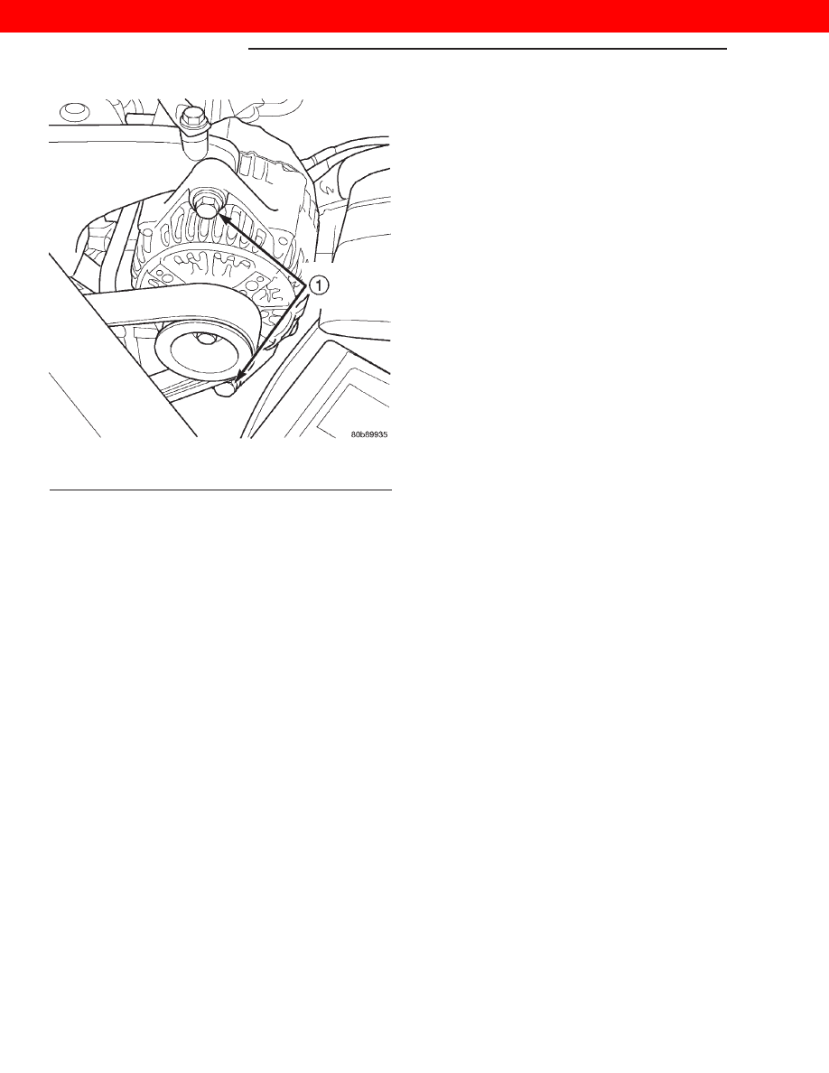
Fig. 2 Generator Mounting Bolts

1 – GENERATOR MOUNTING BOLTS

8C - 2

CHARGING SYSTEM

XJ

REMOVAL AND INSTALLATION (Continued)

2000 JEEP CHEROKEE

IGNITION SYSTEM

TABLE OF CONTENTS

page

page

DESCRIPTION AND OPERATION

IGNITION SYSTEM . . . . . . . . . . . . . . . . . . . . . . . . 1
DISTRIBUTOR-2.5L ENGINE. . . . . . . . . . . . . . . . . 2
SPARK PLUGS . . . . . . . . . . . . . . . . . . . . . . . . . . . 2
SPARK PLUG CABLES-2.5L ENGINE . . . . . . . . . . 2
IGNITION COIL-2.5L ENGINE . . . . . . . . . . . . . . . . 3
IGNITION COIL—4.0L ENGINE. . . . . . . . . . . . . . . 3
CRANKSHAFT POSITION SENSOR. . . . . . . . . . . . 4
CAMSHAFT POSITION SENSOR-2.5L ENGINE. . . 4
CAMSHAFT POSITION SENSOR—4.0L

ENGINE . . . . . . . . . . . . . . . . . . . . . . . . . . . . . . . 5

IGNITION SWITCH AND KEY LOCK

CYLINDER . . . . . . . . . . . . . . . . . . . . . . . . . . . . . 5

DIAGNOSIS AND TESTING

DISTRIBUTOR CAP-2.5L ENGINE. . . . . . . . . . . . . 6
DISTRIBUTOR ROTOR-2.5L ENGINE . . . . . . . . . . 6
SPARK PLUG CABLES . . . . . . . . . . . . . . . . . . . . . 7
SPARK PLUG CONDITIONS . . . . . . . . . . . . . . . . . 8
IGNITION SWITCH AND KEY LOCK

CYLINDER . . . . . . . . . . . . . . . . . . . . . . . . . . . . . 9

REMOVAL AND INSTALLATION

SPARK PLUG CABLES . . . . . . . . . . . . . . . . . . . . 10

SPARK PLUGS . . . . . . . . . . . . . . . . . . . . . . . . . . 10
IGNITION COIL—2.5L ENGINE. . . . . . . . . . . . . . 12
IGNITION COIL—4.0L ENGINE. . . . . . . . . . . . . . 12
CRANKSHAFT POSITION (CKP) SENSOR . . . . . 13
CAMSHAFT POSITION SENSOR—2.5L

ENGINE . . . . . . . . . . . . . . . . . . . . . . . . . . . . . . 14

CAMSHAFT POSITION SENSOR—4.0L

ENGINE . . . . . . . . . . . . . . . . . . . . . . . . . . . . . . 15

DISTRIBUTOR—2.5L ENGINE . . . . . . . . . . . . . . 17
IGNITION SWITCH AND KEY CYLINDER . . . . . . 20
SHIFTER/IGNITION INTERLOCK . . . . . . . . . . . . . 22

SPECIFICATIONS

IGNITION TIMING. . . . . . . . . . . . . . . . . . . . . . . . 23
ENGINE FIRING ORDER—2.5L 4-CYLINDER

ENGINE . . . . . . . . . . . . . . . . . . . . . . . . . . . . . . 23

ENGINE FIRING ORDER—4.0L 6-CYLINDER

ENGINE . . . . . . . . . . . . . . . . . . . . . . . . . . . . . . 23

SPARK PLUGS . . . . . . . . . . . . . . . . . . . . . . . . . . 23
SPARK PLUG CABLE RESISTANCE . . . . . . . . . . 23
IGNITION COIL RESISTANCE—2.5L ENGINE . . 23
IGNITION COIL RESISTANCE—4.0L ENGINE . . 23
TORQUE CHART . . . . . . . . . . . . . . . . . . . . . . . . . 24

DESCRIPTION AND OPERATION

IGNITION SYSTEM

DESCRIPTION

Two different ignition systems are used. One type

is used for the 2.5L 4–cylinder engine. The other is
used for the 4.0L 6–cylinder engine.

OPERATION

2.5L 4–Cylinder Engine:
The ignition system is controlled by the Powertrain

Control Module (PCM).

The ignition system consists of:
• Spark Plugs

• Ignition Coil

• Secondary Ignition Cables

• Distributor (contains rotor and camshaft position

sensor)

• Powertrain Control Module (PCM)

• Crankshaft Position, Camshaft Position, Throt-

tle Position and MAP Sensors

4.0L 6–Cylinder Engine:
The 4.0L 6–cylinder engine uses a one-piece coil

rail containing three independent coils. Although cyl-
inder firing order is the same as 4.0L engines of pre-
vious years, spark plug firing is not. The 3 coils dual-
fire the spark plugs on cylinders 1–6, 2–5 and/or 3–4.
When one cylinder is being fired (on compression
stroke), the spark to the opposite cylinder is being
wasted (on exhaust stroke). The one-piece coil bolts
directly to the cylinder head. Rubber boots seal the
secondary terminal ends of the coils to the top of all
6 spark plugs. One electrical connector (located at
the rear end of the coil rail) is used for all three coils.

Because of coil design, spark plug cables (second-

ary cables) are not used on either engine. A distrib-
utor is not used 
with the 4.0L engine.

The ignition system is controlled by the Powertrain

Control Module (PCM).

The ignition system consists of:
• Spark Plugs

• Ignition Coil(s)

• Powertrain Control Module (PCM)

XJ

IGNITION SYSTEM

8D - 1

• Crankshaft Position Sensor

• Camshaft Position Sensor

• The MAP, TPS, IAC and ECT also have an effect

on the control of the ignition system.

DISTRIBUTOR-2.5L ENGINE

DESCRIPTION

The 2.5L engine is equipped with a camshaft

driven mechanical distributor (Fig. 1) containing a
shaft driven distributor rotor. The distributor is also
equipped with an internal camshaft position (fuel
sync) sensor (Fig. 1).

OPERATION

The distributor does not have built in centrifugal

or vacuum assisted advance. Base ignition timing
and all timing advance is controlled by the Power-
train Control Module (PCM). Because ignition timing
is controlled by the PCM, base ignition timing is
not adjustable.

The distributor is locked in place by a fork with a

slot located on the distributor housing base. The dis-
tributor holddown clamp bolt passes through this slot
when installed. Because the distributor position is
locked when installed, its rotational position can not
be changed. Do not attempt to modify the dis-
tributor housing to get distributor rotation.
Distributor position will have no effect on igni-
tion timing. The position of the distributor will
determine fuel synchronization only.

All distributors contain an internal oil seal that

prevents oil from entering the distributor housing.
The seal is not serviceable.

SPARK PLUGS

DESCRIPTION

Resistor type spark plugs are used.
Spark plug resistance values range from 6,000 to

20,000 ohms (when checked with at least a 1000 volt
spark plug tester). Do not use an ohmmeter to
check the resistance values of the spark plugs.
Inaccurate readings will result.

OPERATION

To prevent possible pre-ignition and/or mechanical

engine damage, the correct type/heat range/number
spark plug must be used.

Always use the recommended torque when tighten-

ing spark plugs. Incorrect torque can distort the
spark plug and change plug gap. It can also pull the
plug threads and do possible damage to both the
spark plug and the cylinder head.

Remove the spark plugs and examine them for

burned electrodes and fouled, cracked or broken por-
celain insulators. Keep plugs arranged in the order
in which they were removed from the engine. A sin-
gle plug displaying an abnormal condition indicates
that a problem exists in the corresponding cylinder.
Replace spark plugs at the intervals recommended in
Group O, Lubrication and Maintenance

Spark plugs that have low mileage may be cleaned

and reused if not otherwise defective, carbon or oil
fouled. Also refer to Spark Plug Conditions.

CAUTION: Never use a motorized wire wheel brush
to clean the spark plugs. Metallic deposits will
remain on the spark plug insulator and will cause
plug misfire.

SPARK PLUG CABLES-2.5L ENGINE

DESCRIPTION

Spark plug cables are used only on the 2.5L

engine. They are sometimes referred to as secondary
ignition wires.

OPERATION

The spark plug cables transfer electrical current

from the ignition coil(s) and/or distributor, to individ-
ual spark plugs at each cylinder. The resistive spark
plug cables are of nonmetallic construction. The
cables provide suppression of radio frequency emis-
sions from the ignition system.

Fig. 1 Distributor and Camshaft Position Sensor-

2.5L Engine

1 – SYNC SIGNAL GENERATOR
2 – CAMSHAFT POSITION SENSOR
3 – PULSE RING
4 – DISTRIBUTOR ASSEMBLY

8D - 2

IGNITION SYSTEM

XJ

DESCRIPTION AND OPERATION (Continued)

IGNITION COIL-2.5L ENGINE

DESCRIPTION

A single ignition coil is used with the 2.5L 4–cylin-

der engine. The coil is not oil filled. The coil windings
are embedded in an epoxy compound. This provides
heat and vibration resistance that allows the coil to
be mounted on the engine.

OPERATION

The Powertrain Control Module (PCM) opens and

closes the ignition coil ground circuit for ignition coil
operation.

Battery voltage is supplied to the ignition coil pos-

itive terminal from the ASD relay. If the PCM does
not see a signal from the crankshaft and camshaft
sensors (indicating the ignition key is ON but the
engine is not running), it will shut down the ASD cir-
cuit.

Base ignition timing is not adjustable. By con-

trolling the coil ground circuit, the PCM is able to set
the base timing and adjust the ignition timing
advance. This is done to meet changing engine oper-
ating conditions.

IGNITION COIL—4.0L ENGINE

DESCRIPTION

A one-piece coil rail assembly containing three

individual coils is used on the 4.0L 6–cylinder engine
(Fig. 2). The coil rail must be replaced as one assem-
bly. The bottom of the coil is equipped with 6 individ-
ual rubber boots (Fig. 2) to seal the 6 spark plugs to
the coil. Inside each rubber boot is a spring. The
spring is used for a mechanical contact between the
coil and the top of the spark plug. These rubber boots
and springs are a permanent part of the coil and are
not serviced separately.

(1) The coil is bolted directly to the cylinder head

(Fig. 3). One electrical connector (located at rear of
coil) is used for all three coils.

OPERATION

Although cylinder firing order is the same as 4.0L

Jeep engines of previous years, spark plug firing is
not. The 3 coils dual-fire the spark plugs on cylinders
1–6, 2–5 and/or 3–4. When one cylinder is being fired
(on compression stroke), the spark to the opposite
cylinder is being wasted (on exhaust stroke).

Battery voltage is supplied to the three ignition

coils from the ASD relay. The Powertrain Control
Module (PCM) opens and closes the ignition coil
ground circuit for ignition coil operation.

Base ignition timing is not adjustable. By con-

trolling the coil ground circuit, the PCM is able to set
the base timing and adjust the ignition timing

Fig. 2 Ignition Coil Assembly—4.0L 6–Cylinder

Engine

1 – CYL. #6
2 – CYL. #5
3 – CYL. #4
4 – CYL. #3
5 – CYL. #2
6 – CYL. #1
7 – COILS (3)
8 – MOUNTING BOLTS (4)
9 – BOLT BASES (4)
10 – RUBBER BOOTS (6)

Fig. 3 Coil Location—4.0L Engine

1 – COIL RAIL
2 – COIL MOUNTING BOLTS (4)
3 – COIL
4 – COIL ELECTRICAL CONNECTION

XJ

IGNITION SYSTEM

8D - 3

DESCRIPTION AND OPERATION (Continued)


Content   ..  91  92  93  94   ..